9 Electrical CAM
DVP-PM Application Manual
9-13
9.2.3.2 Start / Stop Acyclic E-CAM
In cyclic E-CAM, Master and Slave operate according to the user-defined E-CAM Data only when E-CAM
start signal (START0/PG0) is triggered. Unlike cyclic E-CAM, acyclic E-CAM operates only one cycle for
each triggered signal, i.e. E-CAM Data operates only once for one triggered signal.
Before selecting START0 as the start signal, M1035 has to be set ON for setting STOP0/START0 as the
external input. After M1035 is set OFF, M1746 = OFF will enable START0 as the start signal of acyclic
E-CAM rather than PG0.
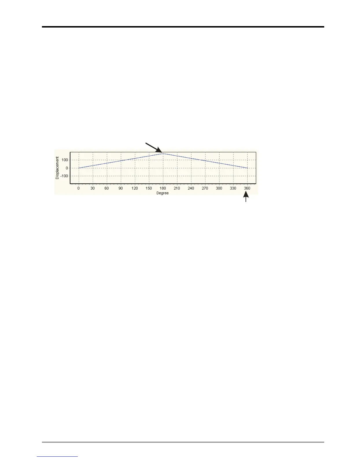
E-CAM Data
Slave
max=180
Slave unit
Master =360max
()
Master unit
Start Acyclic E-CAM
The timing diagram below indicates an operation process of acyclic E-CAM operation with synchronized
output position between 60~300.
1. In T1, D1846 bit 14 = ON, acyclic E-CAM is enabled
2. After the initialization interval of T2, M1812 = ON to indicate the completion of E-CAM initialization. At
this time Slave is still not activated.
3. In T3, acyclic operation starts after START0/PG0 (Input terminal for enabling acyclic E-CAM) is ON.
When M1746 = ON, PG0 is the start signal of acyclic E-CAM; when M1746 = OFF and M1035 = ON,
START0 is the start signal of acyclic E-CAM. In this case Slave starts to operate a cycle according to
the E-CAM Data. (“M1035 = ON” enables START0 / STOP0 as the external input point).
4. When the cycle is completed at T4, DVP-PM will clear the state of M1812 = ON. In addition, users can
also confirm the E-CAM completion by ON state of M1813.
5. In T5, you can decide whether to set ON M1812 for confirming the next E-CAM completion.
6. In T6 and T7, actions of T3~T4 will be repeated. Please note that the interval for enabling acyclic
E-CAM should be longer than 5ms.
7. CLR0 outputs according to the upper/lower bound of sync output during each E-CAM cycle.

 Loading...


