9 Electrical CAM
DVP-PM Application Manual
9-42
Step 1: Add 2 sets of E-CAM charts and set the resolution as 600.
Step 2: Download the below program in DVP-20PM and execute.
Step 3: Set M0 to write the parameters for rotary cut E-CAM into D100~D112 and CR#10000 into D0. In
addition, write the data in D100~D112 into special register CR#10000 to generate the 1
st
rotary cut E-CAM
curve
Step 4: Set M1 to change the data in D102, D104 and D111. Write the modified data into special register
CR#10000 to generate the 2
nd
rotary cut E-CAM curve.
Step 5: Stop the DVP-PM and upload the program.
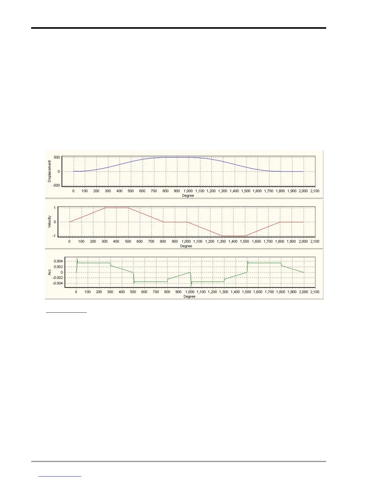
Step 6: Monitor the uploaded E-CAM Chart-0, which is the generated flying saw E-CAM curves.
Ladder Diagram:

 Loading...


