9 Electrical CAM
DVP-PM Application Manual
9-43
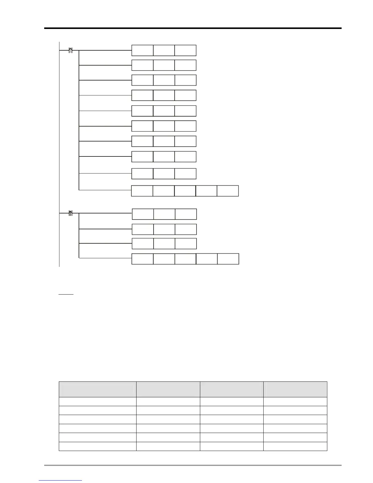
DFLT K1 D106
M0
DMOV K1000 D100
DFLT
K10
D108
DMOV K10000 D0
DMOV K500 D102
DMOV K200 D104
MOV
K0
D110
MOV
H4000
D111
DTO K100 D0 D100 K7
M1
DMOV K-500 D102
DMOV K200 D104
MOV
HC000
D111
DTO K100 D0 D100 K7
MOV
K0
D112
Application Example 3: Multi-cutter application
Setup
:
In multi-cutter application, such as rotary cut with 3 cutters, the pulses per round of Slave can not be evenly
distributed to each cutter and the error of Slave will increase as the execution times increase. In this case,
the CAM data of each cutter should be designed respectively and the sum of the data length of 3 cutters
should equal to total pulses per round.
To meet this requirement, we only need to design the data setting of the first E-CAM once and set up the
associated register for borrowing the data setting from the previous E-CAM curve. By this function, the 3
CAM curves can be well connected and the pulses per round of Slave can be fulfilled. The set values of the
3 E-CAM are as below.
Parameters
SV of 1
st
rotary cut
E-CAM
SV of 2
nd
rotary cut
E-CAM
SV of 3
rd
rotary cut
E-CAM
Length of Master 1000 1000 1000
Length of Slave 333 333
334
Length of sync area 200 200 200
Magnification ratio 1.0 1.0 1.0
Max magnification ratio 10.0 10.0 10.0
Acceleration curve 0 0 0

 Loading...


