9 Electrical CAM
DVP-PM Application Manual
9-45
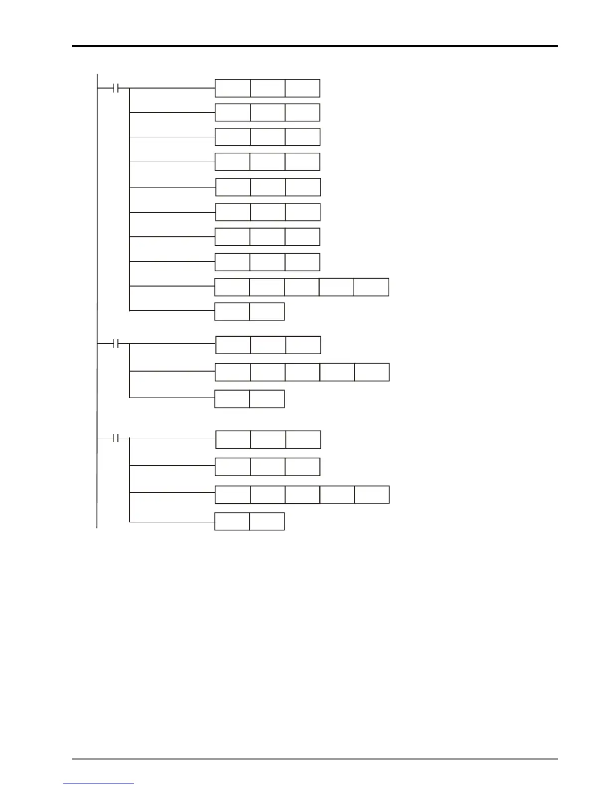
M100
DMOV K1000 D100
DMOV K10000 D0
DMOV K333 D102
DMOV K200 D104
Create the first E-CAM data
MOV
K0
D110
MOV
H0
D111
DTO K100 D0 D100 K7
M101
MOV H8000 D111
DTO K100 D0 D100 K7
Borrow the data setting of previous E-CAM curve
Create the second E-CAM data
RST
M100
RST
M101
M102
DMOV K334 D102
DTO K100 D0 D100 K7
Set up length of Slave: 3334(pulse)
Create the third E-CAM data
RST
M102
Set up length of Master
Set up length of Slave
Set up length of sync area
Set up magnification ratio
Set up max magnification of speed
Set up acceleration curve
Set up CAM curve
DFLT
K1
D106
DFLT K10 D108
MOV
H8000 D111
Borrow the data setting of previous E-CAM curve
9.4.2.4 Thick Material Cutting
In above rotary cut application, there is only one contact point for the cutter and the material, regardless of
the thickness of the material. In this way, only one synchronizing point is required when designing the
E-CAM. For thick material cutting, such as soap or steel plate, the velocity relationship between cutter
dropping and the material moving should be considered. When the material enters the sync area, the
material moving speed will equal to the moving speed of cutter, ensuring that the cutting plane is flat and
vertical to the conveyor. The below diagram illustrates the operation angles between the cutter the material.
V1 is the material moving speed; V2 is the cutter dropping speed; and the grey curves indicate sync area
(cutting area). When the thickness of material is equal, the contact angle between the cutter and the material
(angle θ) is a fixed value. In addition, the cutting angle α varies during the cutting process. The velocity

 Loading...


