9 Electrical CAM
DVP-PM Application Manual
9-46
relationship can be described by the equation below:
)sin(
1
1
2
θα
+
=
V
V
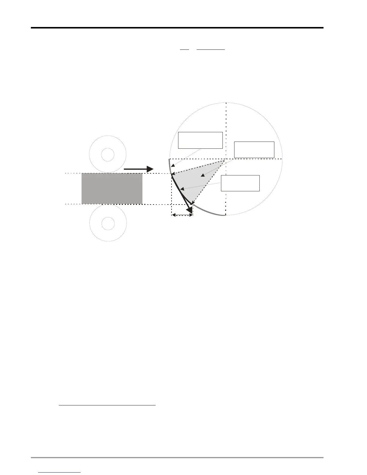
. According to the diagram below,
the cutter rolls through non-sync area and syn area. In sync area, the horizontal moving distance (L) of the
cutter should be the same as the moving distance of the material, and the horizontal moving distance can be
obtained by the equation:
. In non-sync area, users can set up the
acceleration/deceleration speed according to the cut length of material.
Material Feeding Axis (Master)
α
Horizontal moving distance: L
Non-sync
area
Sync area
θ
V1
V2
Cutting area
Material
Futhermore, the starting position (angle) of the cutter should also be considered by the number of cutters on
the cutting axis. If the total pulses of cutting axis can be equally divided by the cutters, i.e. even number of
cutters shares even number of pulses, the pulses required for single cutter can be obtained. Convert the
obtained pulses into degrees and the starting position as well as the end position can be obtained, which are
the required parameters for setting thick material cutting. On the other hand, if the total pulses of cutting axis
can not be equally divided by the cutters, i.e. even number of pulses for odd number of cutters, angle θ and
the length of Master before sync area for single cutter should be set up respectively to obtain the starting
and end position of each cutter.
Also, care should be taken on setting the contact angle, which is related to the thickness of the material and
the vertival position of the cutting device. When setting the contat angle, make sure the contact angle is a
little smaller or equal to the actual contact angle otherwise an arc cutting plane will be generated. On the
othe hand, the sync end angle should also be a little bigger or equal to the actual sync end angle for
ensuring that a smooth and flat cutting plane can be obtained.
The settings of two cases are explained here below.
z Case 1: Pulses can be equally divided:
For even number of cutters, select “Equally divide non-sync area” function by bit0 of Data 1, and DVP-PM
will automatically calculate the required pulses for each cutter. As the below diagram, in actual settings only
2 parameters including “Sync start angle” and Sync end angle” are required for calculating the angle of sync
area
α and the angle of non-sync area θ.

 Loading...


