2
360
-
360
÷
⎟
⎟
⎠
⎞
⎜
⎜
⎝
⎛
⋅×
⎟
⎟
⎠
⎞
⎜
⎜
⎝
⎛
=
roundperPulses
cuttersofNumber
roundperPulses
roundperPulses
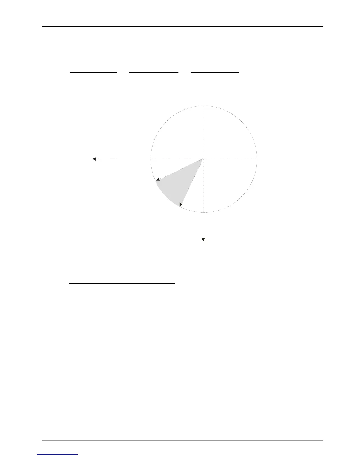
αθ
α
θ
θ
180
90
0 or 360
270
Sync start angle
Sync end angle
End position of the cutter
Start position
of the cutter
The actual adjustment steps are: 1. select the sync start and sync end angle; 2. align the cutter with the start
position of the cutter; 3. Execute E-CAM operation; 4. Inspect the cutting plane on material. If the cutting
plane is bended, conduct fine tuning on the sync start/end angle until the cutting plane is flat and smooth.
z Case 2: Pulses can NOT be equally divided:
If the total pulses of Slave can not be equally divided by the cutters, angle θ
1
and the length of Master
before sync area should be specified respectively in E-CAM setting, so that the starting and end position of
each cutter can be obtained. As the diagram below, parameters including angle θ
1
, length of Master before
sync area, sync start angle and sync end angle should be specified respectively. In addition, the pulses
required for each cutter should also be specified in E-CAM setting. When the above parameters are ready,
run the thick material cutting E-CAM and conduct fine-tuning on the parameters of each cutter until the best
results are obtained.

 Loading...


