9 Electrical CAM
DVP-PM Application Manual
9-51
Step 1: Run the program and read the E-CAM status by DFROM instruction. Read the data in CR#10001 of
special module K100 to D100~D108.
Step 2: Set M3 to write the length of Slave into D126 and the initial Slave error into D128. Calculate the real
error, i.e. difference between the increased error and the initial error, and take the half of Slave length as the
reference.
Step 3: When the real error is between “± half of Slave length”, take the real error as the offset value directly.
Step 4: When the real error exceeds “± half of Slave length”, follow the below rule:
⎪
⎩
⎪
⎨
⎧
×+=⇒−<
×=⇒>
ratio OffsetSlave of lengtherror RealOffsetSlave of length error Real
ratio OffsetSlave of lengtherror RealOffsetSlave of length error Real
)(
2
1
)-(
2
1
Step 5: Set M4 to calculate the modified length of Slave with offset compensation.
Step 6: When M4 is reset, fill the original length of Slave back to D302.
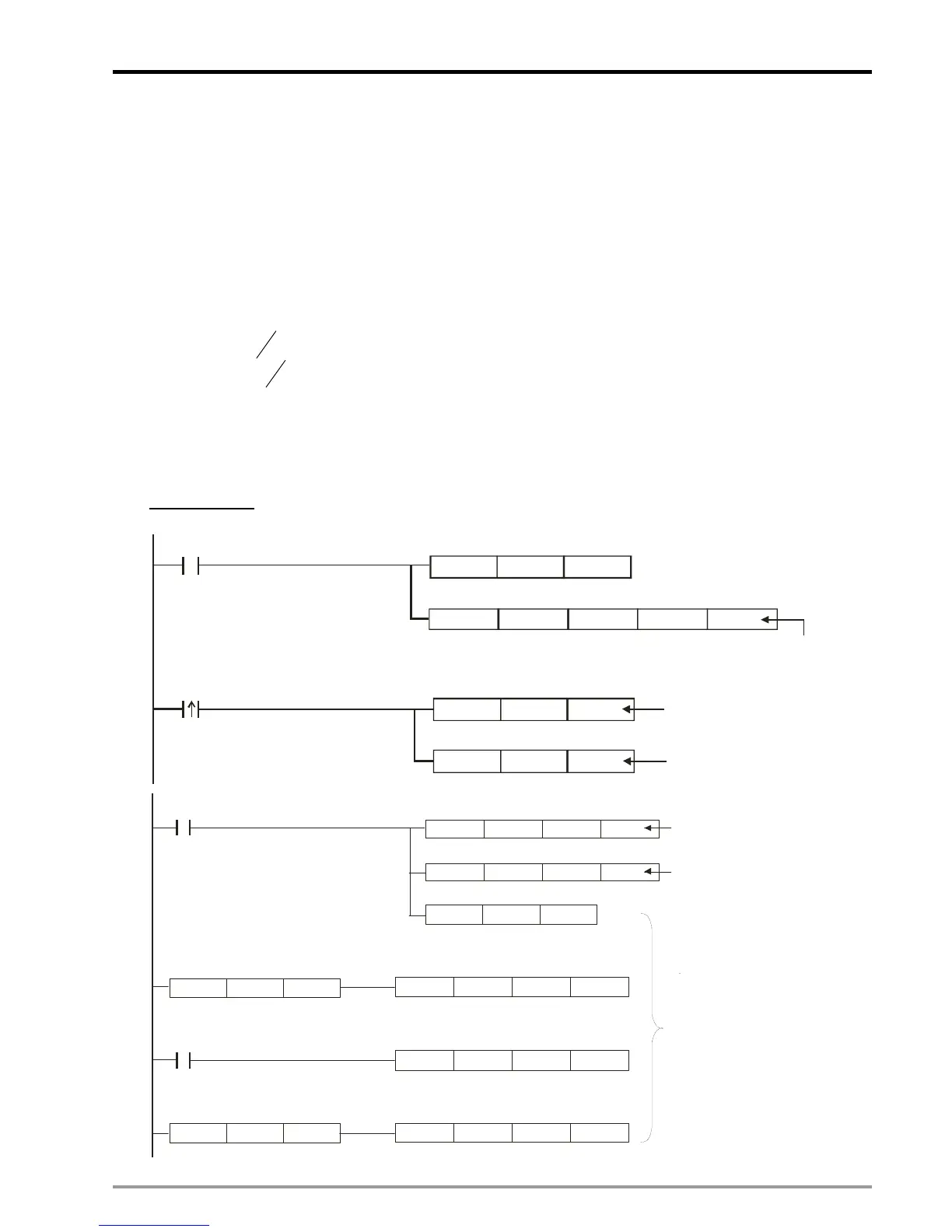
Ladder Diagram
:
M1000
M3
DMOV
K10001 D0
DFROM K100
D0 D100 K5
DMOV D302 D126
D108
D128
DMOV
Backup initial value of D108
Length of Slave
Backup D302
Backup D108 in D128
Read the error between
DOG signal and the end point
of Slave position (D108)
DSUB
D108
D128 D130
DDIV
D126
K2
D132
DMOV
D130 D138
DSUB
D130
D126
D138
DSUB D132
K0 D136
DADD
D130
D126
D138
M1000
M3
"
D132 = 1/2*D126
D136 = -1/2*D126
.
..
..
..
DLD<
D130
D136
DLD>
D130
D132
Take the difference
between D108 (initial error)
and D128 (increased error)
Take D132 and D136
as the criteria for judging
1. If D130 (real error)is between
D132 and D136, backup D130 in
D138 directly
2. If D130 is bigger than D132
,subtract D130 with D126 and
store the result in D138.
3. If D130 smaller than D136
, add D130 with D126 and store
the result in D138
D138 is the offset value for
compensation

 Loading...


