3 Functions of Devices in DVP-PM
DVP-PM Application Manual
3-23
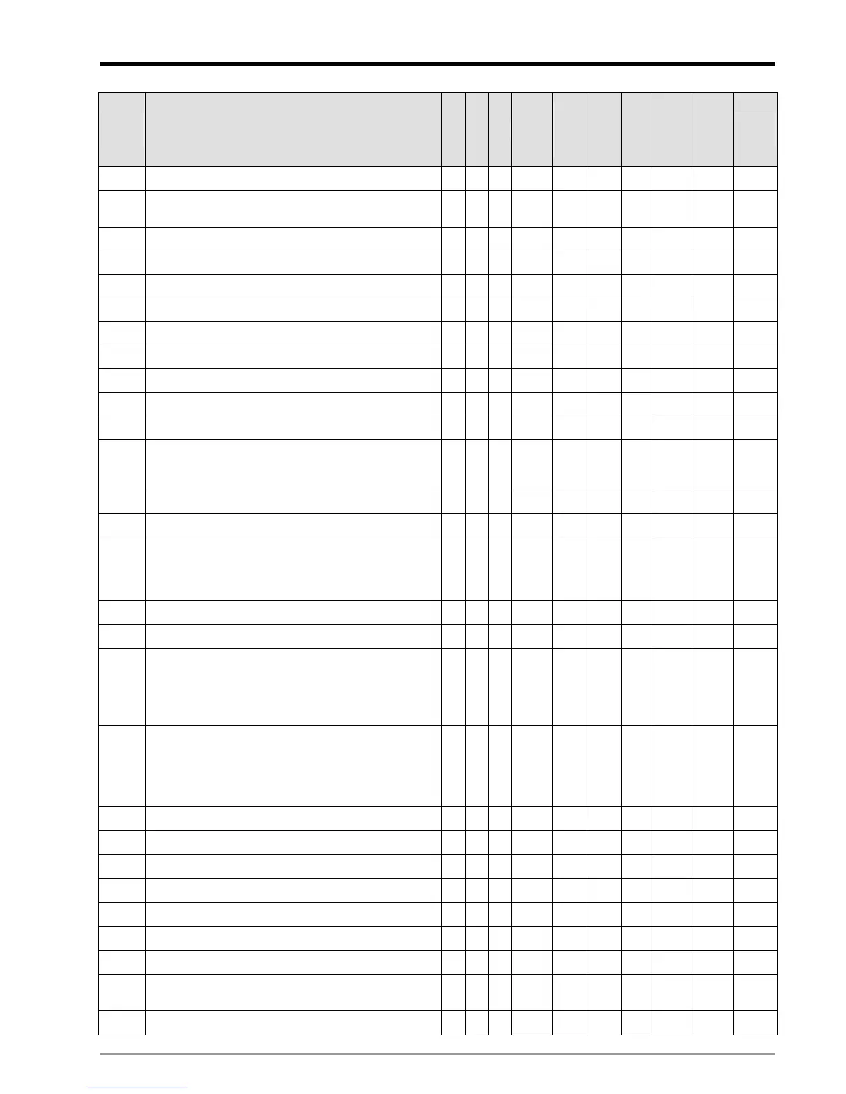
Special
D
Function
10M 20D 20M
OFF
Ø
ON
MANU
Ø
AUTO
AUTO
Ø
MANU
Attrib. Latched Default
Page
number
D1000* Scanning watch dog timer (Unit: 1ms)
○ ○ ○
200 - - R/W NO 200 3-35
D1005
Display the firmware version of DVP-PM (initial factory
setting)
○ ○ ○
# - - R NO # -
D1002 Program capacity
○ ○ ○
65,535 - - R NO 65,535 -
D1003 Sum of the PLC internal program memory
○ ○ ○
- - - R YES 0 -
D1008 Step address when WDT is ON
○ ○ ○
0 - - R NO 0 -
D1010 Current scan time (unit: 1ms)
○ ○ ○
0 - - R NO 0 -
D1011 Minimum scan time (unit: 1ms)
○ ○ ○
0 - - R NO 0 -
D1012 Maximum scan time (unit: 1ms)
○ ○ ○
0 - - R NO 0 -
D1020* X0 ~ X7 input filter (unit: ms)
○ ○ ○
10 - - R/W NO 10 3-36
D1025 Error code of communication request error
○ ○ ○
0 0 - R NO 0 -
D1036* COM1 (RS-232) Communication protocol
○ ○ ○
H’86 - - R/W NO H’86 3-36
D1038*
Delay time setting for data response when PLC is
Slave in RS-485 communication. Range:0~3000 (unit:
10ms)
○ ○ ○
- - - R/W YES 0 3-39
D1039* Fixed scan time (ms)
○ ○ ○
0 - - R/W NO 0 3-39
D1040 The cycle tme setting to synchronize with DVP-FPMC
○ ○ ○
0 - - R/W NO 0
D1050
↓
D1055
Converted data for Modbus communication data
processing. PLC automatically converts the ASCII data
in D1070~D1085 into Hex data and stores the 16-bit
Hex data into D1050~D1055
○ ○ ○
0 - - R NO 0 -
D1056 CH0 present value of function card 2AD
○ ○ ○
0 # - R NO 0 -
D1057 CH1 present value of function card 2AD
○ ○ ○
0 # - R NO 0 -
D1070
↓
D1085
Feedback data (ASCII) of Modbus communication.
When PLC’s RS-485 communication instruction
receives feedback signals, the data will be saved in the
registers D1070~D1085. Usres can check the received
data in these registers.
○ ○ ○
0 - - R
NO
0 -
D1089
↓
D1099
The sent data of Modbus communication. When PLC’s
RS-485 communication instruction sends out data, the
data will be stored in D1089~D1099. Users can check
the sent data in these registers.
○ ○ ○
0 - - R
NO
0 -
D1109* COM3 (RS-485/RS232) Communication protocol
○ ○ ○
H‘86 - - R/W
NO
H’86 3-36
D1110 CH0 average value of function card 2AD
○ ○ ○
0 # - R
NO
0 -
D1111 CH1 average value of function card 2AD
○ ○ ○
0 # - R
NO
0 -
D1116 CH0 output value of function card 2DA
○ ○ ○
0 - - R/W
NO
0 -
D1117 CH1 output value of function card 2DA
○ ○ ○
0 - - R/W
NO
0 -
D1120* COM2 (RS-485) communication protocol
○ ○ ○
H’86 - - R/W
NO
H’86 3-36
D1121 DVP-PM communication address (latched)
○ ○ ○
- - - R/W YES 1 -
D1122
COM2(RS-485) Residual number of words of
transmitting data
○ ○ ○
0 0 - R
NO
0 -
D1123
COM2(RS-485) Residual number of words of the
○ ○ ○
0 0 - R
NO
0 -
 Loading...


