3 Functions of Devices in DVP-PM
DVP-PM Application Manual
3-49
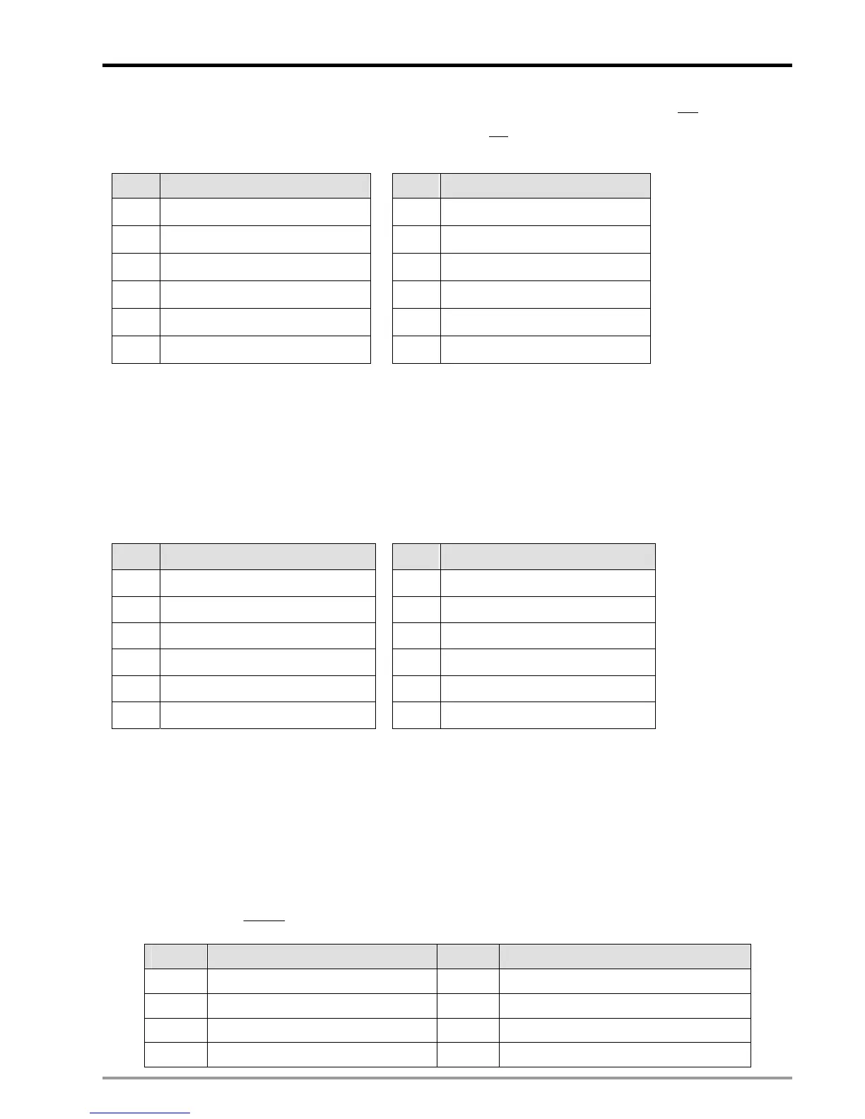
For input terminals below, setting the corresponding bit# to be ON will define the input terminal as NO
contact; setting
the corresponding bit# to be OFF will define the input terminal as NC
contact.
20PM: 10PM:
bit#
Polarity of input terminal
0 PG2
1 MPGB1
2 MPGA1
3 LSN2
4 LSP2
5 DOG2
bit#
Polarity of input terminal
0 X3(DOG3)
1 MPGB1
2 MPGA1
3 X2(DOG2)
4 X1(DOG1)
5 X0(DOG0)
Function Group:
Reading Input terminal status 2 (for Z-axis)
Number:
D1805
Explanations:
When there is signal input at the input terminal, the corresponding bit# = ON. If not, the corresponding bit# = OFF
20PM: 10PM:
bit# Input terminal status
0 PG2
1 MPGB1
2 MPGA1
3 LSN2
4 LSP2
5 DOG2
bit# Input terminal status
0 X3(DOG3)
1 MPGB1
2 MPGA1
3 X2(DOG2)
4 X1(DOG1)
5 X0(DOG0)
Function Group:
Filter coefficient
Number:
D1806
Explanations:
1. The low byte of D1806 sets the filter coefficient of the input terminals START, STOP, DOG, LSN, LSP and PG
2. The high byte of D1806 sets the filter coefficient of the inut terminal MPG0/MPG1.
3. Filter coefficient
4N
2
85000
+
= (KHz), N = 1~19; the conversion results are as below:
N kHz N kHz
1 2656.25 11 2.593994
2 1328.125 12 1.296997
3 664.0625 13 0.648499
4 332.0313 14 0.324249
 Loading...


