3 Functions of Devices in DVP-PM
DVP-PM Application Manual
3-50
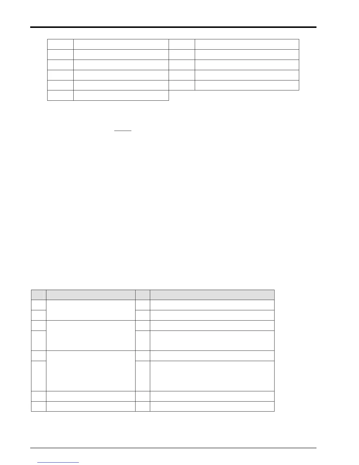
5 166.0156 15 0.162125
6 83.00781 16 0.081062
7 41.50391 17 0.040531
8 20.75195 18 0.020266
9 10.37598 19 0.010133
10 5.187988
4. When D1806 = 0, the filter function on external terminals will be disabled.
5. For example, if D1806 is set as H0A0A, the filter coefficient on input terminals START, STOP, DOG, LSN, LSP
and PG and MPG0/1 will be:
5.187988
2
85000
410
=
+
(KHz), i.e. input frequency higher than 5.187988KHz will be
filtered out.
Function Group:
Error Status of O100
Number:
M1953, D1802, D1803
Explanations:
1. When errors occur in O100 program, O100 error flag M1953 will be ON, the error code will be stored in D1802,
and error step will be stored in D1803.
2. See the table of error messages in Appendix of Chapter 14.
Function Group:
Parameter Setting of X-Y-Z-A Axis
Number:
D1816, D1896, D1976, D2056
Explanations:
Parameter setting of X axis: D1816, Y axis: D1896, Z axis: D1976 and A axis: D2056. See the tables below:
bit# X-Y-Z axis parameter setting bit# X-Y-Z axis parameter setting
0 8 Zero return direction (*4)
1
Unit (*1)
9 Zero return mode (*4)
2 10 DOG signal rising/falling edge triggered (*4)
3
Multiplication of position data (*2)
11
Reverse the displacement direction in same
pulse output polarity (*4)
4 12 Relative/absolute positioning (*4)
5
Pulse type (*3)
13
DOG signal rising/falling edge triggered (for
single/ 2 speed positioning interruption mode)
(*4)
6* PWM mode (*4) 14 Curve selection (*4)
7 15
Note: PWM mode is only applicable for DVP-10PM
Note *1:
 Loading...


