Chapter 6 Control TerminalsME300
Transistor output terminals (MO1, MCM)
Make
sure to connect the digital outputs to the correct polarity. See the wiring
diagram when connecting a relay to the digital output, connect a surge absorber
across the coil, and check the polarity.
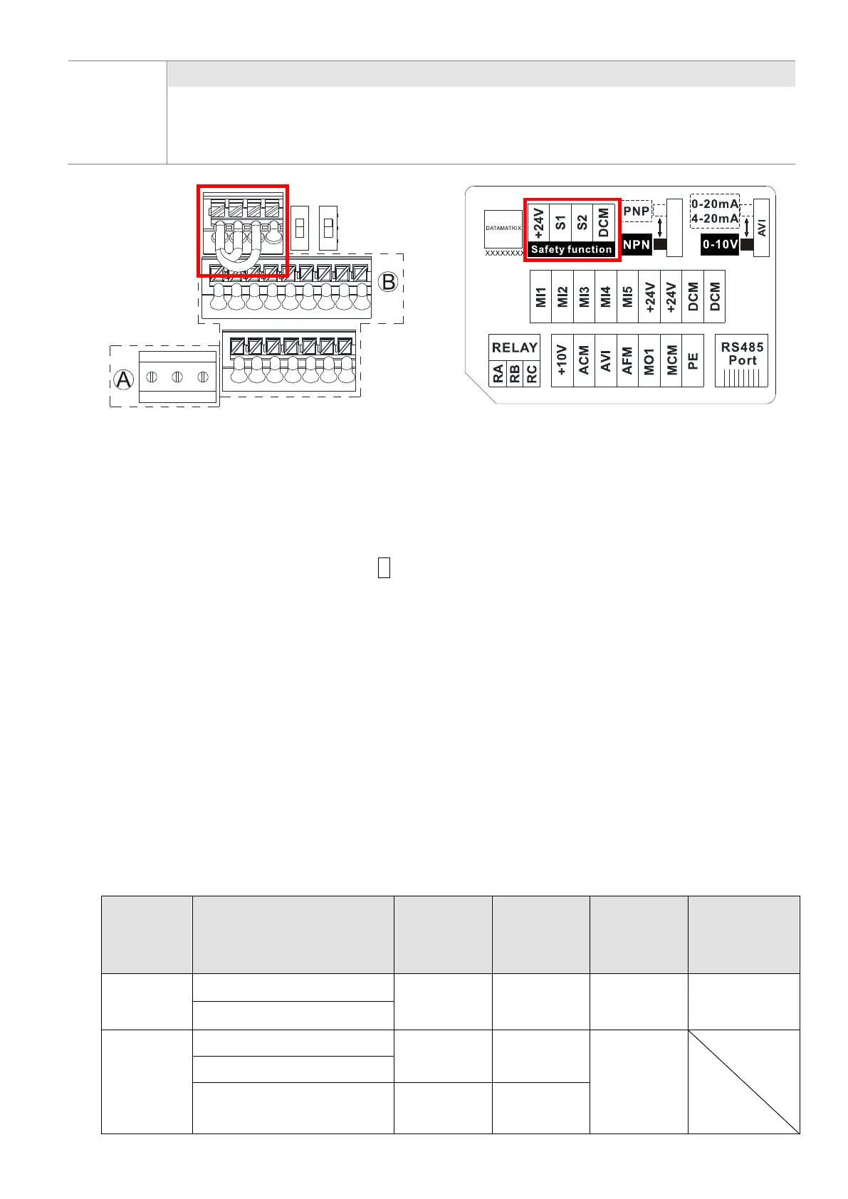
Control Terminal Distribution Diagram
Control Terminal Location Map
Wiring precautions:
As 1. and 2. shows in the figure above, +24 V, S1, S2, and DCM are for built-in STO models only.
The default condition is +24 V / S1 / S2 shorted by jumper of build-in STO model, as 1. shows in the
figure above. Refer to Chapter 4 WIRING for more details.
Build-in STO model: VFD_ _ _ME_ _A_ S AA.
The +24 V of safety function is for STO only, as 1. and 2. shows in the figure above, and cannot be
used for other purpose.
The RELAY terminal uses the PCB terminal block (as area A shows in the figure above):
1. Tighten the wiring with a 2.5 mm (wide) x 0.4 mm (thick) slotted screwdriver.
2. The ideal length of stripped wire at the connection side is 9–10 mm.
3. When wiring bare wires, make sure they are perfectly arranged to go through the wiring holes.
The Control terminal uses a spring clamp terminal block (as area B
shows in the figure above):
1. When removing wires, use the slotted screwdriver to press down the terminal, and the suggested
force is 1.5 kgf.
2. Slotted screwdriver: 2.5 mm width and 0.4 mm thickness
3. When wiring bare wires, make sure they are perfectly arranged to go through the wiring holes.
Wiring Specifications of Control Terminals
Function
name
Conductor cross section
Stripping
length (mm)
Maximum
Wire Gauge
Minimum
Wire Gauge
Screw size
Tightening
torque (±10%)
RELAY
Terminals
solid wire
9–10
1.5 mm
2
[16 AWG]
0.2 mm
2
[24 AWG]
[4.3 lb-in.]
stranded wire
Control
Terminals
solid wire
9
0.75 mm
2
[18 AWG]
0.2 mm
2
[24 AWG]
stranded wire
Stranded with ferrules with
plastic sleeve
9
0.5 mm
2
[20 AWG]

 Loading...


