Explanatory Photos for DISASSEMBLY
• The angles from which the photos are taken are shown by "
Photo angle: A, B, C, D
".
• See the diagram below about the shooting direction of each photograph.
• Photographs with no shooting direction indicated were taken from the top of the unit.
• The photograph is AVR-S700E3 model.
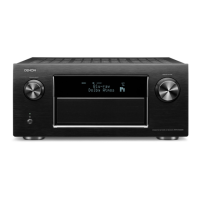
The viewpoint of each photograph
(Shooting direction:X)
[
View from the top
]
Caution:
・
Before disassembling this unit, be sure to discharge the power line (the colored line in the schematic diagram).
・
FFC cables with one end disconnected should be insulated by using tapes, etc.
1. FRONT PANEL ASSY
Proceeding : TOP COVER
→
FRONT PANEL ASSY
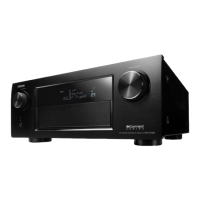
(1) Remove the screws.
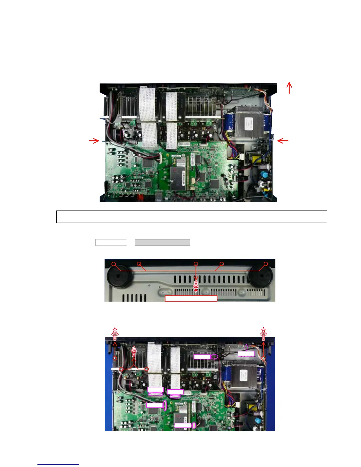
(2) Remove the connector wire and FFC. Remove the screws.
Front side
Shooting
direction: D
Shooting
direction: C
↑Shooting direction: A↑
↓Shooting direction: B↓
 Loading...