ABOUT THIS MANUAL
.............................................................3
What you can do with this manual ............................................3
Using Adobe Reader (Windows version) ..................................4
SAFETY PRECAUTIONS
..........................................................6
NOTE FOR SCHEMATIC DIAGRAM
.........................................7
NOTE FOR PARTS LIST
...........................................................7
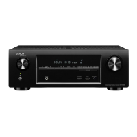
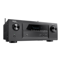
TECHNICAL SPECIFICATIONS for AVR-X1100W
..................9
DIMENSION for AVR-X1100W
.................................................9
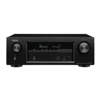
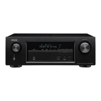
TECHNICAL SPECIFICATIONS for AVR-S700W
..................10
DIMENSION for AVR-S700W
.................................................10
Precautions During Service
...................................................11
Initializing This Unit .................................................................11
Service Jigs ............................................................................. 11
DISASSEMBLY
........................................................................12
1. FRONT PANEL ASSY ........................................................13
2. DIGITAL PCB .....................................................................14
3. RADIATOR ASSY ...............................................................15
4. SMPS PCB .........................................................................15
5. REGULATOR PCB .............................................................15
6. TRANS POWER ................................................................15
SPECIAL MODE
......................................................................16
Special Mode Conguration Buttons (for AVR-X1100W) .........16
Special Mode Conguration Buttons (for AVR-S700W) ..........17
1. Version Display Mode ........................................................18
2. PANEL / REMOTE LOCK Selection Mode .........................22
3. Selection Modes for Service-related Operations ................23
DIAGNOSTIC PATH DIAGRAM .........................................27
4. Remote ID Setup Mode ......................................................49
5. Protection Pass Mode ........................................................50
6. CX870 / CY920 Reboot mode ............................................50
7. CX870 / CY920 Initialization mode ....................................51
Service Jigs
.............................................................................52
Procedure after Replacing the Microprocessor, etc.
..........54
Firmware Update Procedure
..................................................54
1. Updating by USB ................................................................54
2. Updating by DPMS .............................................................63
ADJUSTMENT
.........................................................................70
SURROUND MODES AND PARAMETERS
............................71
TROUBLE SHOOTING
............................................................74
1. POWER ..............................................................................74
2. Analog video ......................................................................75
3. HDMI/DVI ...........................................................................76
4. AUDIO ................................................................................78
5. Network/Bluetooth/USB .....................................................81
6. SMPS .................................................................................84
CLOCK FLOW & WAVE FORM IN DIGITAL BLOCK
.............86
LEVEL DIAGRAM
....................................................................87
BLOCK DIAGRAM
...................................................................93
POWER DIAGRAM
..................................................................94
WIRING DIAGRAM
..................................................................95
PRINTED WIRING BOARDS
...................................................96
SCHEMATIC DIAGRAMS (1/19)
...........................................100
SCH01_HDMI_RX ................................................................100
SCH02_HDMI ADV7623 .......................................................101
SCH03_HDMI_TX .................................................................102
SCH04_DIGITAL SUPPLY ....................................................103
SCH05_MCU ........................................................................104
SCH06_MCU_LEVEL_CHG .................................................105
SCH07_DIR_PLD .................................................................106
SCH08_DSP .........................................................................107
SCH09_MAIN DAC ...............................................................108
SCH10_NETWORK ..............................................................109
SCH11_FRONT_HDMI .........................................................110
SCH12_ANALOG .................................................................. 111
SCH13_ADAPTER ................................................................112
SCH14_BLUETOOTH ........................................................... 113
SCH15_DIFF-AMP ................................................................ 114
SCH16_MAIN ........................................................................115
SCH17_FRONT ....................................................................116
SCH18_REGULATOR ...........................................................117
SCH19_SMPS ......................................................................118
EXPLODED VIEW
.................................................................119
PACKING VIEW
.....................................................................121
SEMICONDUCTORS
.............................................................122
1. IC's ...................................................................................122
2. FL DISPLAY .....................................................................148
CONTENTS
2
 Loading...
