ADJUSTMENT
Adjusting Idling Current
1. Preparation
(1) Prepare a DV voltmeter.
(2) Place the unit in normal usage conditions, away from highly ventilated areas such as next to an air conditioning ma-
chine or electric fan.
The set requires an ambient temperature of 15
℃
to 30
℃
and standard humidity.
(3) Settings of This Unit
• POWER (Power source switch) STANDBY
• SPEAKER (Speaker terminal) No load
( Do not connect equipment such as speakers or dummy resistors. )
2. Adjustment Procedure
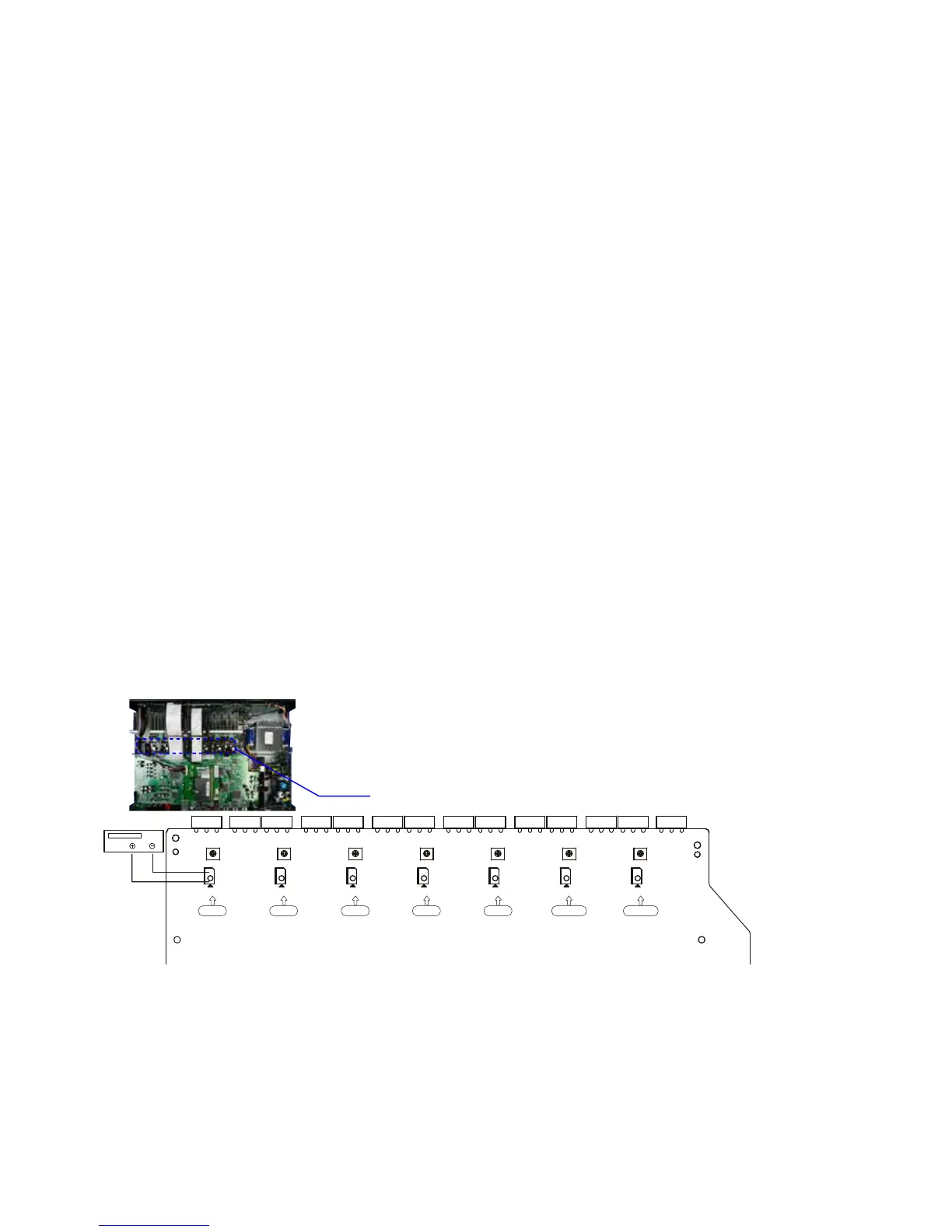
(1) Remove the top cover and turn VR550, VR540, VR530, VR520, VR510, VR570 and VR560 of the AMP PCB as far
anticlockwise(
c
) as possible.
(2) Connect the DC Voltmeter test points.
FRONT-Lch
:
CN510
FRONT-Rch
:
CN550
CENTER ch
:
CN530
SURROUND-Lch
:
CN520
SURROUND-Rch
:
CN540
SURROUND-BACK Lch
:
CN560
SURROUND-BACK Rch
:
CN570
(3) Connect the power cord to an outlet. Next, press the power button to turn on the power.
(4) Set this unit as follows.
MASTER VOLUME : "---" anticlockwise (
c
min.)
SPEAKER (Speaker terminal)
:
No load
( Do not connect equipment such as speakers or dummy resistors. )
MODE
:
MCH STEREO
FUNCTION
:
DVD
(5) Turn VR550 clockwise (
x
) and adjust the voltage of the test point to "
6.0mV ± 0.5mV DC
" within 2 minutes.
(6) 10 minutes after the preliminary adjustment, turn VR550 and set the voltage as "
8.0mV ± 0.5mV DC
".
(7) Adjust the variable resistance of each channel using the same method.
F Rch S Rch C Rch S Lch F Lch S Back Rch S Back Lch
VR550 VR540 VR530 VR520 VR510 VR570 VR560

 Loading...