22
DCD-CX3
⑧ In the monitor terminal setting mode:
Press the or button to select Y and press the to decide it. And then press the or button to
select ZZ and press the to decide it. (When set at Y = 1, press the button to switch ZZ in the order 01, 02, 03, 04,
05, 06, 09, 0A, 01 Åc.) If the or buttons are pressed after setting, switches to selecting Y mode. (When Y = 1 is
selected, the previously selected ZZ value is displayed.)
The set values are not cleared even when the STOP button is pressed or when the and buttons are pressed simulta-
neously.
Remaining buffer capacity: PWM output of the remaining data capacity to the DRV2 terminal.
(Notes: The remaining buffer capacity is the remaining data capacity, not the remaining free space. Also, the DRV2 terminal is also
used for tray driving, so when outputting the remaining buffer capacity, be careful not to drive the tray.)
When Y = 2 or 3, if ZZ = 0C is selected, Dfesv (FE stored value) is output to the MONI 1 terminal, Tfesv (TE stored value) is output
to the MONI 2 terminal and Dassv (AS stored value) is output to the MONI 3 terminal.
Y = 1 : RF signal monitor setting (ANAMONI 1 and 2)
= 2 : Digital signal monitor setting (MONI 0 and 1)
= 3 : Digital signal monitor setting (MONI 2 and 3)
= 4 : Digital signal monitor setting (MONI 4 and 5)
= 5 : Digital signal monitor setting (MONI 6 and 7)
= 6 : Remaining buffer capacity output setting (DRV2)
ZZ : When Y = 1: 01 to 06, 09, 0A
When Y = 2: 06 to 08, 0A, 0B, 0C
When Y = 3: 06 to 08, 0A, 0B, 0C
When Y = 4: 07 to 0F
When Y = 5: 07 to 0F
When Y = 6: No setting
4th place : During Y selection, " * " displayed at 4th place.
7th place : During ZZ selection, " * " displayed at 7th place.
When both Y and ZZ are set, " * " displayed at 4th and 7th places.
⑨ Checking the SACD watermark signal quality mode:
Press the or button to select Y and press the to decide it
Y = 1 : PSP amplitude ( Addr = 0x51 readout )
Hexadecimal, displayed as 2-byte data.
= 2 : Monitor setting ( Addr = 0x38, Data = 0x06 setting )
MNIT2 terminal : Sector Detect Error
MNIT1 terminal : PDM Detect
MNIT0 terminal : PSP-DATA OK
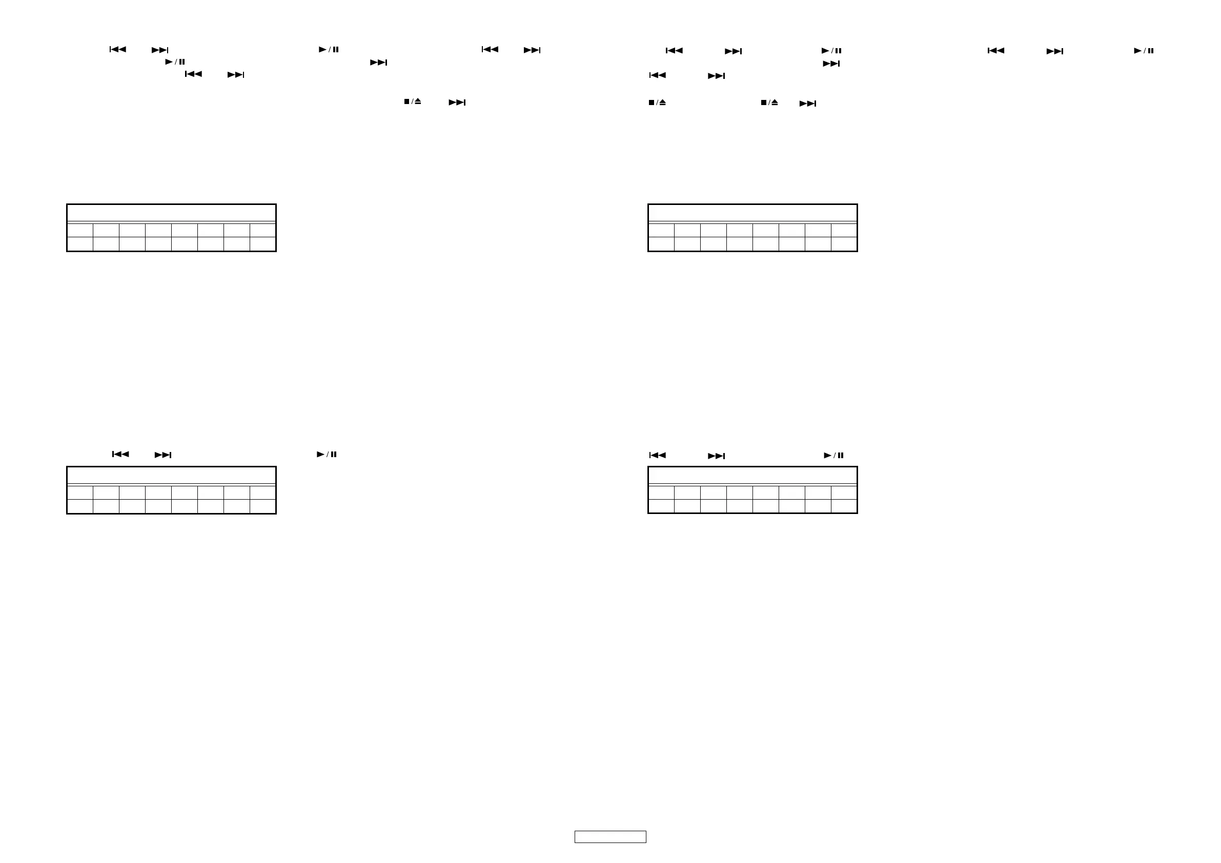
FLDisplay(Thedisplaypartof8digits)
12345678
TDY―ZZ――
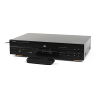
FLDisplay(Thedisplaypartof8digits)
12345678
TEY―xxxx
⑧モニタ端子設定モード
Y を または ボタンで選択し、 ボタンで確定します。次に ZZ を または ボタンで選択、 ボ
タンで確定します。(Y=1 で確定した場合、 ボタンでZZ が 01,02,03,04,05,06,09,0A,01…の順で切替わります。)確定後
または ボタンを押すと、Y 設定モードに切換わります。(Y=1 を選択した場合、前回設定した ZZ 値が表示され
ます。)
ボタン押し、または と ボタンの同時押ししても、設定値はクリアされません。
バッファ残容量の出力は、DRV2 端子にデータの残容量を PWM で出力します。
注 : バッファ残容量は、データの残容量であり、空きサイズではないので注意してください。また、DRV2 端子は、TRAY 駆
動用にも使用しているため、バッファ残容量を出力する場合は、TRAY が駆動しないよう注意してください。)
Y=2 または 3 の時に ZZ=0C が選択された場合は、MONI1 端子に Dfesv(FE 保存値 )、MONI2 端子に Dtesv(TE 保存値 )、MONI3
端子に Dassv(AS 保存値 ) を出力します。
Y =1 : RF 信号モニタ設定(ANAMON1,2)
=2 : Digital 信号モニタ設定 (MONI0,1)
=3 : Digital 信号モニタ設定 (MONI2,3)
=4 : Digital 信号モニタ設定 (MONI4,5)
=5 : Digital 信号モニタ設定 (MONI6,7)
=6 : バッファ残容量出力設定 (DRV2)
ZZ : Y=1 の時 01 〜 06,09,0A
Y=2 の時06 〜 08,0A,0B,0C
Y=3 の時06 〜 08,0A,0B,0C
Y=4 の時07 〜 0F
Y=5 の時07 〜 0F
Y=6 の時指定なし
4 桁目 : Y 選択中の場合、" * " を表示します。
7 桁目 : ZZ 選択中の場合、" * "を表示します。
Y と ZZ の両方確定時は、4 桁目と 7 桁目に " * " を表示しまする。
⑨ SACD ウォーターマーク信号の品質を確認モード
または ボタンで Y を選択し、 ボタンで確定します。
Y =1 : PSPAmplitude(Addr=0x51 の読み出し )
16 進、2 バイトデータとして表示されます。
=2 : モニタ設定 (Addr=0x38,Data=0x06 設定 )
MNIT2 端子:SectorDetectError
MNIT1 端子:PDMDetect
MNIT0 端子:PSP-DATAOK
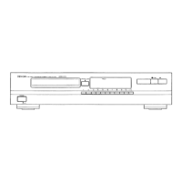
FL 管の表示 (8 桁の表示部 )
12345678
TDY―ZZ――
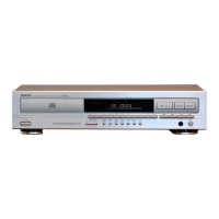
FL 管の表示 (8 桁の表示部 )
12345678
TEY― x x x x