Pressure Switch
The pressure switch sets the water level in the washer. As the water level rises, it compresses the air in
the pressure switch hose. When the washer reaches the desired water level, the compressed air in the
pressure switch hose opens the contacts in the switch, shutting o the water. When at the empty level,
the pressure switch contacts are closed allowing the machine to either spin or ll with water. The 1/4”
screw in the middle of the switch adjusts the water level. Turning it clockwise 1/8 of a turn will raise the
water level 1/4 of an inch. Counter clockwise will lower the water level. Before making any adjustments
of the pressure switch, drain the tub and blow the hose clear of possible water bubbles which can cause
erratic pressure switch operation. With no load, the water level should be approximately at the bottom to
1” up from the bottom of the glass on ALL models.
Add-Bleach LED
This LED light indicates to the user the correct time to add bleach.This LED is polarity sensistive and must
be connected correctly.
Data Communication Cable
Goes between front PCB board and Variable Frequency Drive unit mounted center rear of machine. It has
telephone type connectors at each end and is inserted at Controller PCB and the Variable Frequency Drive.
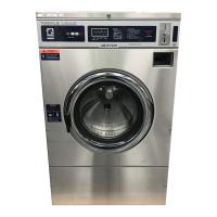
Delta Variable Frequency Drive:
Main power is connected to terminals L1, L2, and L3 on the Delta
drive. If the washer is connected to a three phase source, there
should be voltage present on all three terminals. If the washer is
connected to single phase power, there should be voltage present on
terminals.
The voltage should measure 208 Volts to 240 Volts A.C. between
phases and connected to if connected to three phase). There is a
tolerance of + 10% on the mains voltage (187 Volts to 264 Volts).
Delta VFD Motor Leads:
The wires from the motor are connected to terminals T1, T2, and T3.
Since this drive uses pulse width modulation, an accurate current or
voltage reading is not possible. Although an accurate current reading
is not possible, a balanced current reading should be present while the
motor is running.
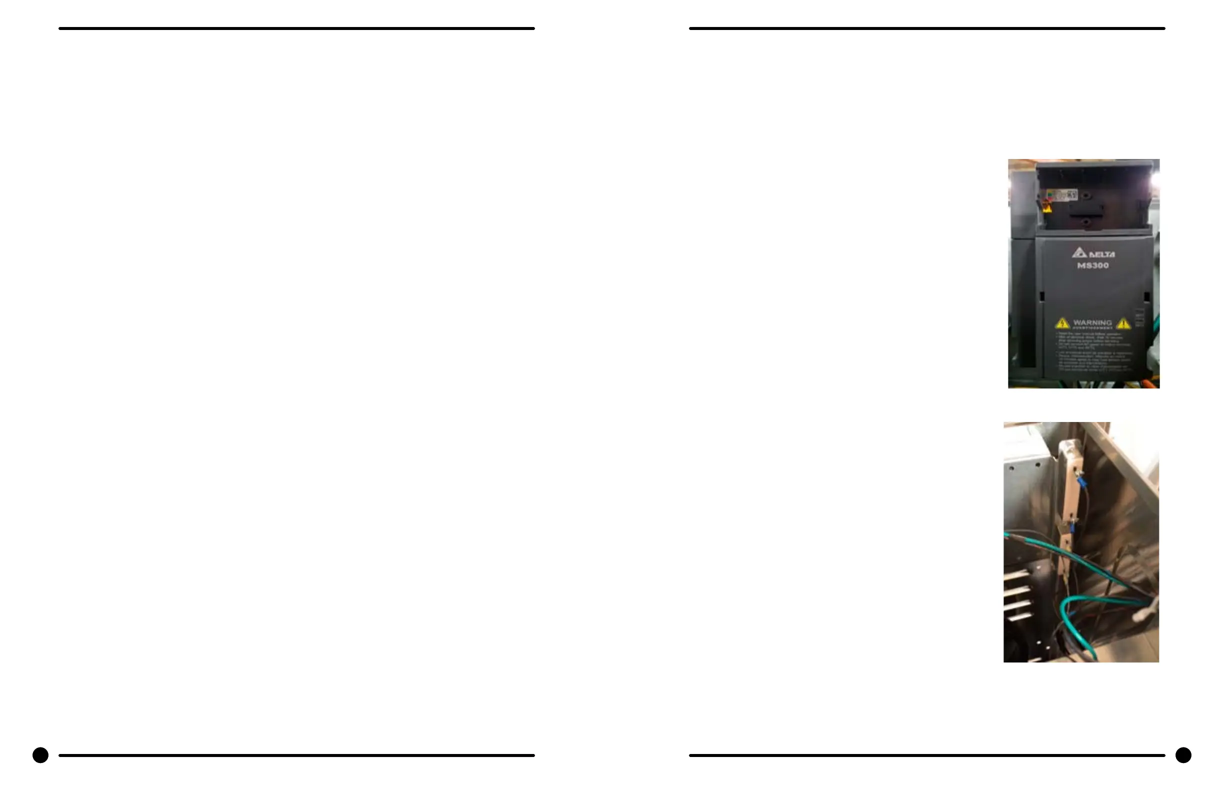
Delta VFD Dynamic Braking Resistors:
Two, 160 Ohm or 200 Ohm braking resistors (Please check your
washer model parts requirements and quantities), are connected
in parallel and attached to the drive at terminals B1 and B2. These
resistors allow voltage, which is generated by the motor when
decelerating, to be dissipated. They will become hot while the motor
is slowing down, so care should be taken so as not to come in contact
with them. This will prevent an electrical shock and/or a physical burn.
Delta VFD Cooling Fan:
There is a cooling fan attached to the bottom of the Delta drive. This
fan will operate when the internal temperature of the drive reaches
a predetermined level, the same way the radiator fan in a newer car
operates. THE FAN CAN OPERATE ANYTIME POWER IS APPLIED TO
THE DRIVE! Remove power to the drive if work is required around the
fan.
70 71
Part # 8533-050-001 2/22 Part # 8533-050-001 2/22