Keeping the hardware identity information (write-protected), IDEPROM allows running the
correct software.
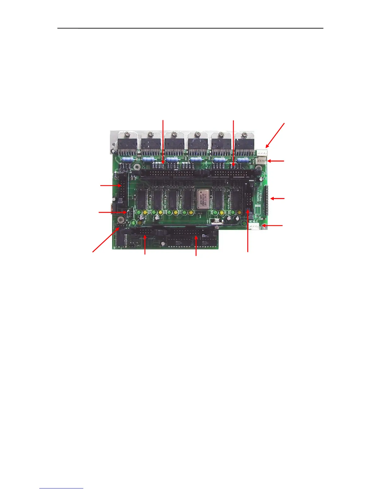
2.1.6. Pneumatic and Power Board (PPB)
PPB card contains the main power regulator circuits, valve and motor driver circuits and other
connections for the fluidic and pneumatic system’s parts.
Power system generates +5V (Digital power), +8V (Printer power) and +12V (Motor and valve
power) from the single +12V DC input signal.
Motor driver part consists of six separated PIC micro-controllers with power drivers. Horizontal,
Vertical and Sample rotor motors have one combined ribbon cable connection. Main Dilutor
(with two motors) and Micro-dilutor have separated connectors.
Valve driver section is based on the valve driver PIC micro-controller and two 8-bit, powered
output shift registers (with built in protection diodes) and there is one common ribbon cable
connection for the valve boards. The peristaltic pump has a separated Darlington driver circuit
for more reliable operation.
2.1.7. Optical boards for stepper motors
There are six stepper motors in the system: Horizontal and Vertical motors, which make the
movements of the sampling needle; the main Dilutor motors (2), which move the syringes
(diluent, lyse, lyse EOS); the micro Dilutor motor, which operates during sampling phase and
the motor moving the sample rotor. The stepper motor opto boards provide connections
between the motor driver ICs and motors, and have opto switches for the motor’s home and end
positions. The actual status of the stepper motor’s optos is indicated by two LEDs on each
stepper motor opto boards.
Dilutor and Micro-dilutor have their own separated opto-board, located directly on the units.
Horizontal and Vertical motors and the sample rotor unit have a common Opto-board, called
XYOpto Board: