4.1.2. Sampling needle setting
This adjustment sets the sampling needle to the operational position.
In Service menu, in Miscellaneous submenu of HM5 select Needle setting.
The software moves the needle back and up, and turns on horizontal and vertical motors to
keep needle in place.
Check the setting of the needle. If end of the needle is at the bottom of the washing head,
needle is set correctly. If not, open screws “B” (see above), and adjust the needle to the bottom
of the washing head. Fasten “B” screws.
Set the end of the tip to the washing head’s bottom plane, while the carriage is held by
motors. (Needle setting menu). Fix the „B” screws.
Be careful with the bent upper end of the sampling needle, because if badly aligned,
during movement it can hit other mechanical components causing mechanical jam,
and therefore damages or error.
4.2. Hardware settings
4.2.1. Amplifier offset setting
Amplifier offset should be between ±5mV. Run self test to determine whether offset is within this
range. If it is out of range, it should be re-set, by the following way.
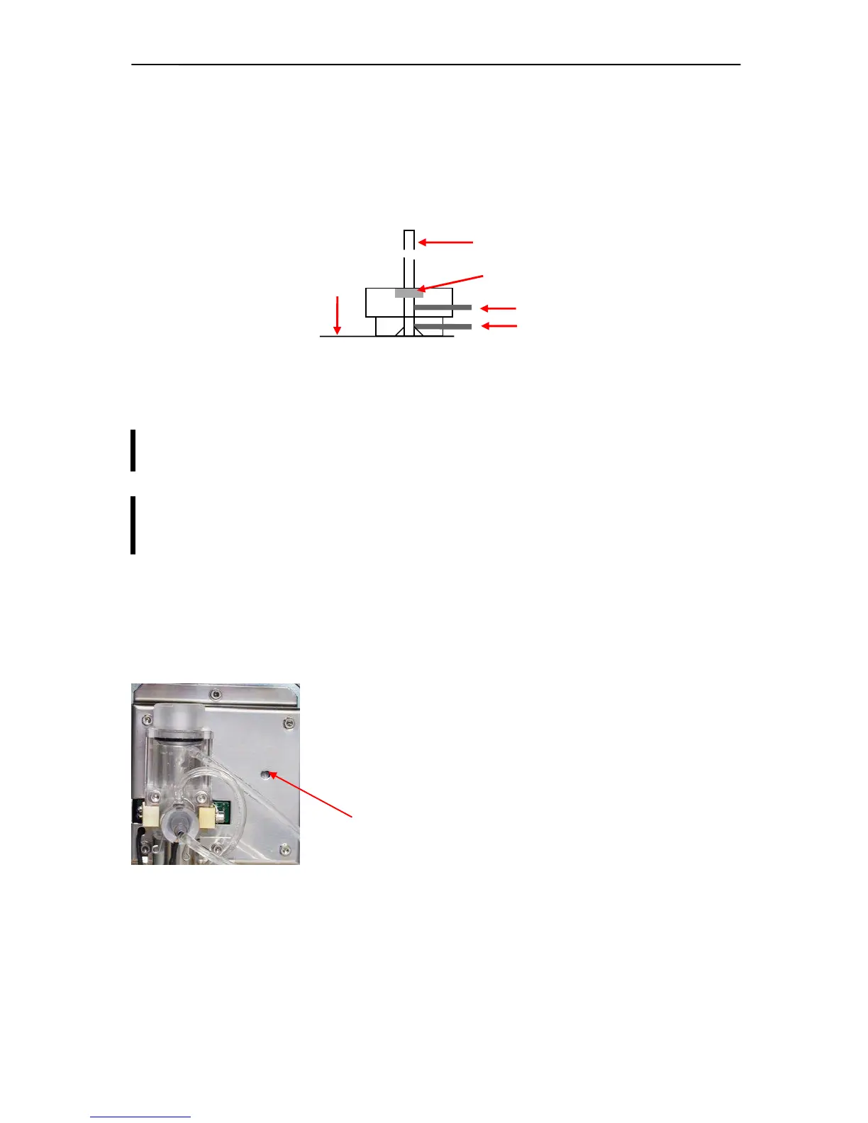
1. Locate the opening for offset setting potentiometer on the
measuring block (see enclosed picture).
2. In Service menu select Offset adjustment menu.
3. Adjust the potentiometer to reach 0 mV.
Opening for offset adjustment on measuring block