There are two kinds of HGB measurements:
Sample measurement (before RBC counting)
Diluent measurement (during WBC washing phase)
The HGB result is calculated from these measurements by:
HGB log (CNT
diluent light
/ CNT
sample light
)
Due to enhanced HGB
technology, ABACUS 4 is less sensitive to incident light
changes. However, it is recommended to keep side door closed during measurements.
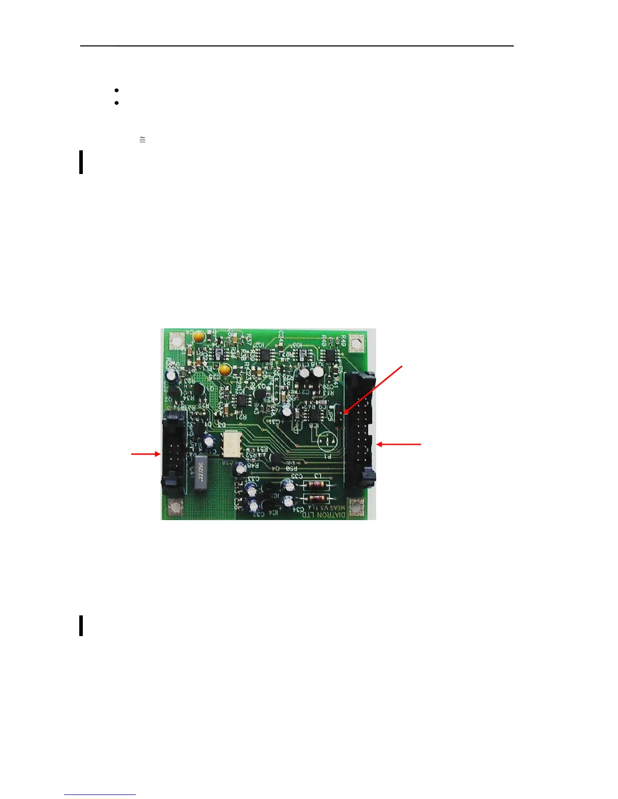
2.1.3. Cell counter Amplifier Board
Amplifier board includes its own voltage regulator, connection interfaces to HGB head, to high
voltage board and to COMB. There is a current generator circuit on this board, which operates
from 50V measuring voltage (generated by High Voltage Board) and the probe voltage (DC) is
amplified with a voltage follower (output: ELV). Nominal measuring current is 870 µA.
Amplifier board includes one input connector for the chamber (measuring electrode). There are
two optical switches (U1, U3) to connect high voltage to the probe with HSW signal and isolate
the input of the amplifier, respectively. Test circuit allows generating test pulses (with TEST and
PLS signals through FETs) for checking the proper operation of the amplifier channel.
Amplifier board includes a 3-stage main amplifier channel, which gains input signal to the 0...5 V
range (this is the input range of the A/D converter, located on the COMB card). The RSW signal
changes the gain (RBC, WBC) in the feedback of the second amplifier stage with U2 (MAX319)
analog switch. There is an offset potentiometer, P1 in the third amplifier stage; the manufacturer
sets the correct offset voltage.
Adjust the offset voltage only in case it is out of the +/- 5mV range.
DHON signal (from the COMB board) switches on the LED and the MVON signal – active during
counting – switches off the Photo Detector in the HGB head, to prevent noise generated by the
HGB detector.
The other side of the amplifier board contains special connectors for the chamber and the HGB
head (JP4).