OPERATOR’S MANUAL
PM300E and PM332E Planter Monitors
11001-1423-200710
ADVANCED SETUP / 25
ACCESSORY SETUP (OPTIONAL)
To add an auxiliary sensor and its performance characteristics (calibration
values, limits, etc.) to the monitoring inputs, it must be activated by entering
a calibration constant. If minimum or maximum alarms are desired, the
limits can be added to the calibrated sensors. A fan, shaft, or flow sensor
can be monitored with HI and/or LOW alarms or no alarm values.
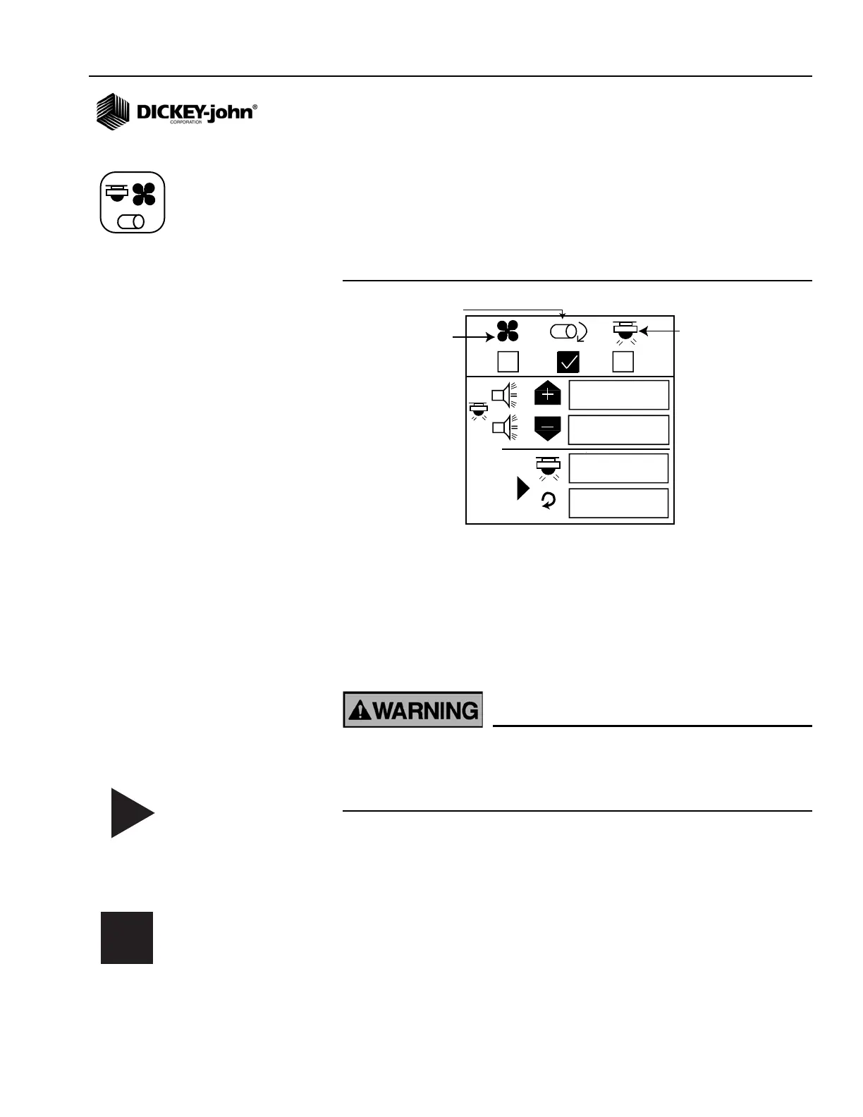
Figure 16
Accessory Screen
To Enter a Calibration Constant:
1. At the Main Menu screen, highlight the Accessory Setup icon and
press Enter.
2. Use the Left and Right key to select fan, shaft or flow symbol.
3. Use the Down Arrow key to change high and low alarm values.
4. Press Enter to highlight digit to change. If the calibration factor is
unknown, the monitor can determine the calibration factor by using the
built-in calibration mode.
Ensure equipment is configured to operate safely. Shaft/fan
calibration requires movement in associated equipment and
revolution counting. Flow calibration requires liquid dispensing,
catching, and measurement.
To Perform a Sensor Calibration:
1. Highlight the Start symbol. Ensure the system is in a safe state.
2. Start the monitor calibration by selecting the Enter key. The Start
symbol (triangle) will change to a Stop symbol (square).
3. Activate the shaft, fan, or flow. Count the revolutions (shaft/fan) or
catch liquid (flow) while the monitor measures pulses.
4. Deactivate the shaft, fan, or flow.
5. Stop the monitor calibration by selecting the Enter key again.
6. Highlight the revolutions or liquid level window.
7. Select the Enter key.
8. Enter the number of revolutions (shaft/fan) or liters (flow).
Accessory Setup icon
Start symbol
Stop symbol