About the development board Peripheral application header
ConnectCore for i.MX51 Hardware Reference Manual
105
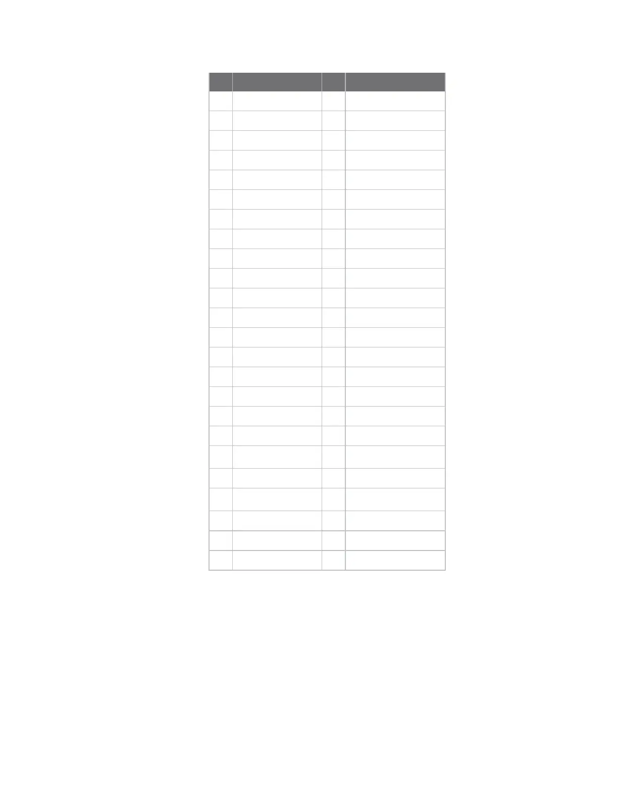
Pin Signal Pin Signal
3 D1 4 D2
5 D3 6 GND
7 D4 8 D5
9 D6 10 D7
11 GND 12 D8
13 D9 14 D10
15 D11 16 GND
17 D12 18 D13
19 D14 20 D15
21 GND 22 8-bit / 16-bit (default)
23 GND 24 +3.3V
25 +3.3V 26 A0
27 A1 28 A2
29 A3 30 GND
31 A4 32 A5
33 A6 34 A7
35 GND 36 A8
37 A9 38 GND
39 CS0# 40 I2C
2
_SDA/GPIO1_3
41 WE# 42 OE#
43 I2C
2
_SCL/GPIO1_2 44 GPIO3_2
45 +3.3V 46 +3.3V
47 BE2# 48 BE3#
49 BCLK 50 GND
The voltage level of the data, address and control signals provided by the module is +1.8V. A level
shifter is provided on the development board to buffer and change the voltage level of most peripheral
application signals on this header to +3.3V.
The Data bus signals D0 - D15 are connected to the i.MX51 data bus signals D16 - D31.
The Address bus signals A0 - A9 are connected to the i.MX51 data/address bus signals DA0 - DA9.
The BE2# signal is connected to the i.MX51 byte enable 2 (D16 - D23).
The BE3# signal is connected to the i.MX51 byte enable 3 (D24 - D31).