About the module Power
ConnectCore for i.MX51 Hardware Reference Manual
41
Power
Module power supplies
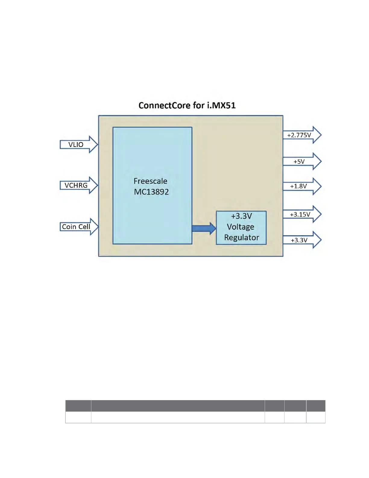
The following figure shows the power supply scheme of the ConnectCore for i.MX51 module.
Supply inputs
The ConnectCore for i.MX51module has the following supply inputs:
n Battery input (VLIO)
n Charger input (VCHRG)
n Coin Cell input (VCC_COINCELL)
Coin cell input (VCC_COINCELL)
The VCC_COINCELL pin allows connection to either a coin cell or a supercap. This permits the RTC to
keep running when the VLIO and VCHRG are at 0 volts. You can program the PMIC to allow current to
be output from this pin while VLIO or VCHRG are present to charge the supercap (or Secondary
Lithium Manganese coin cell). When in charge mode, this pin can output 60uA and the PMIC can be
configured for a charge termination voltage in the range +2.5V to +3.3V.
The following table shows the current draw from the coin cell when there is no main battery attached:
Mode Description Typ Max Unit
RTC All blocks disabled, no main battery attached, coin cell is attached. 36 50 uA