Module specifications Electrical characteristics
ConnectCore for i.MX51 Hardware Reference Manual
133
Interface
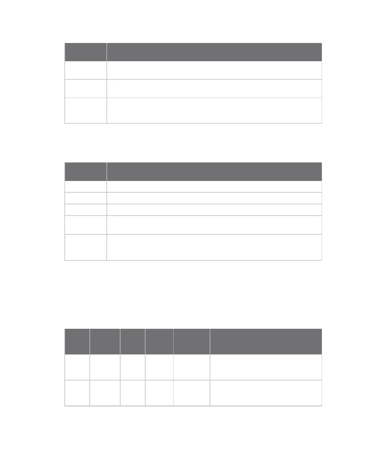
Configuration Interfaces Used
Minimum Console, Ethernet.
+3.3V of development board drawn from external power supply.
Typical VGA, USB Host (two devices connected), Audio, Ethernet, Console.
+3.3V of development board drawn from module.
Maximum Display1, Display2, Camera1, Camera2, USB OTG, USB Host (four devices
connected), Audio, Ethernet, Console, WLAN, SD Card, microSD
™
Card.
+3.3V of development board drawn from module.
The ConnectCore for i.MX51 supports several power modes. The current drawn by the module is highly
dependent on the power modes. To make some current measurements, five different power modes
have been defined:
Interface
Configuration Interfaces Used
Full Load System running at 100% CPU load.
Normal Normal operating state. User interacting with the device.
User Idle After a long period of user inactivity some devices are turned off.
System Idle In this state the user is not using the system, even passively, and devices that are
not actively doing work are turned off.
Suspend This is the sleep state, no threads are running, the CPU is idle, the peripherals are
turned off, and the system can wake up only by means of hardware wake-source
interrupt.
The tables below show the current drawn by the module for the different power modes and the
different interface configurations.
On-module power supplies
The following table provides the on-module power supplies available through the module connectors,
which can be used to supply the components integrated on a customer baseboard.
Supply Source
Output
Voltage
Load
Capacity
Off-module
Available
Current
Comments
+2.775V PMIC
VIOHI
LDO
+2.775V 100mA
max
50mA max Used on module to power IPU, Peripheral
interfaces, Accelerometer, I
2
C, Ethernet
PHY, and bootstraps
+1.8V PMIC
VGEN3
LDO
+1.8V 250mA
max
250mA max