About the development board Power LEDs, LE3, LE4, LE6 and LE7
ConnectCore for i.MX51 Hardware Reference Manual
74
User LEDs, LE49 and LE51
The user LEDs are controlled through applications running on the ConnectCore for i.MX51 module. You
may use these module signals to implement the LEDs:
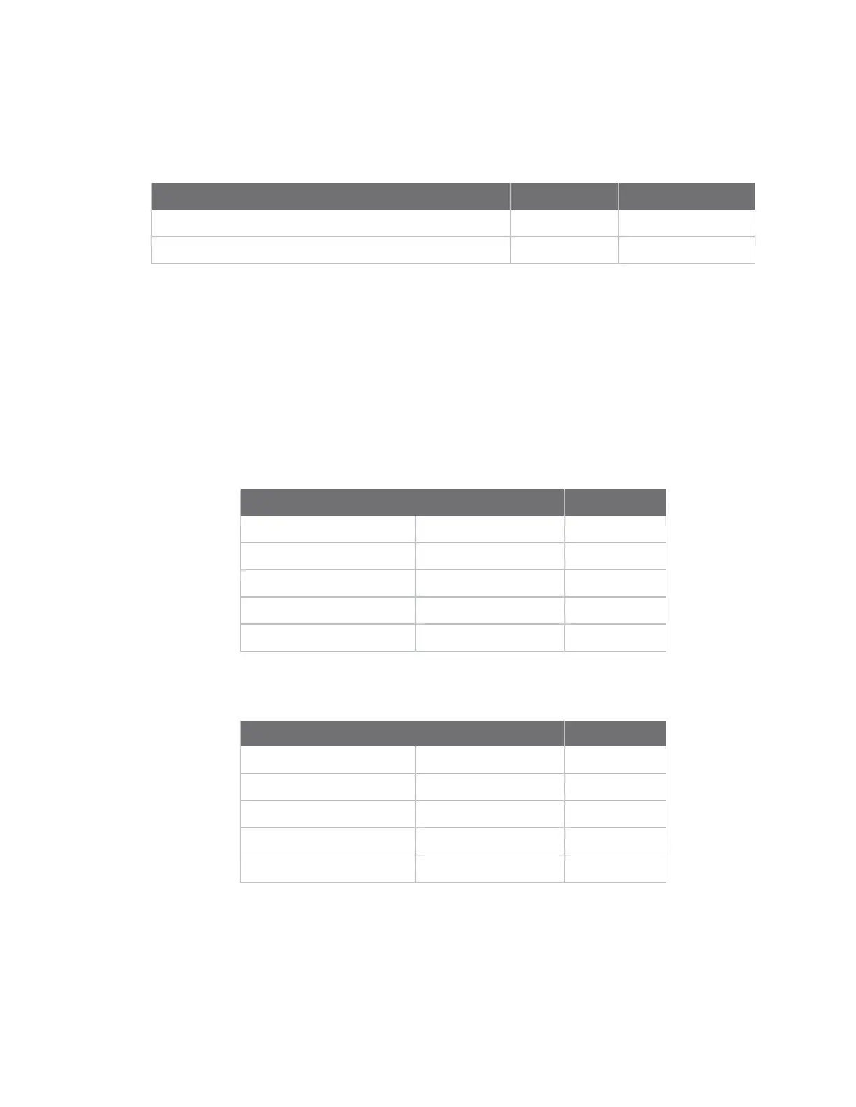
Signal Name LED GPIO Used
NANDF_RB2/MII_COL/SP12_SCLK/GPIO3_10 LE51 GPIO3_10
NANDF_RB1/PATA_IORDY/SPI2_RDY/GPIO3_9 LE49 GPIO3_9
Serial status LEDs
The development board has two sets of serial port LEDs - four for serial port 1 and four for serial port
2. The LEDs are connected to the TTL side of the RS232 or RS4xx transceivers.
n Green means corresponding signal high
n Red means corresponding signal low
n The intensity and color of the LED will change when the voltage is switching
UART 1 status LEDs
LED Reference Function
RED GREEN
LE60 LE45 TXD
LE61 LE46 RXD#
LE62 LE47 RTS#
LE63 LE48 CTS#
UART 2 status LEDs
LED Reference Function
RED GREEN
LE41 LE40 TXD
LE57 LE42 RXD
LE58 LE43 RTS#
LE59 LE44 CTS#
XBee Associate, LE50
This LED is connected to the Associate output of the Digi XBee module. This LED provides information
of the device's network status and diagnostics information. For a more in-depth description of this
LED, refer to the Digi XBee modules documentation available at www.digi.com.