About the development board Power-Over-Ethernet (PoE) - IEEE802.3af
ConnectCore for i.MX51 Hardware Reference Manual
107
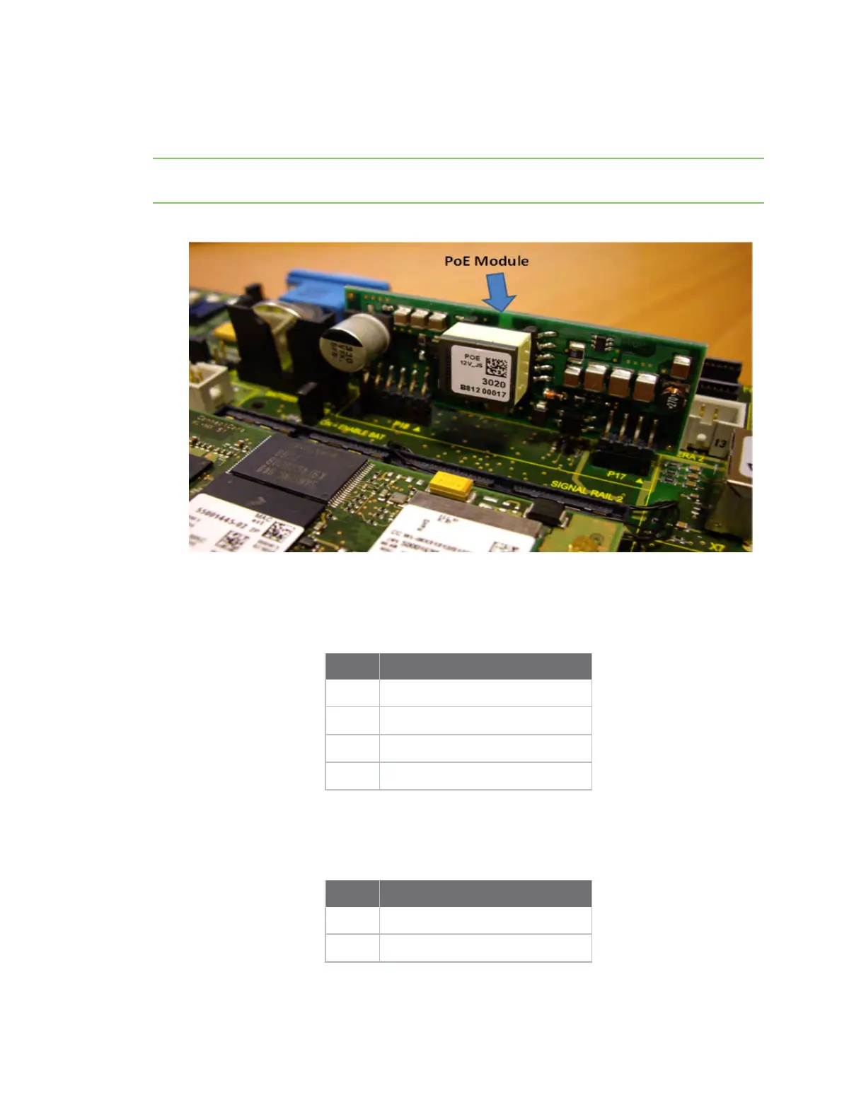
The PoE module
Plug in the PoE module at a right angle to the development board, as shown in the picture below.
Note the PoE module is part of the optional Digi 802.3af application kit (sold separately, Digi P/N DG-
ACC-POE).
PoE connector (power in), P17
The table below provides the pinout of the PoE input connector:
Pin Signal
1 POE_TX_CT
2 POE_RX_CT
3 POE_RJ45_4/5
4 POE_RJ45_7/8
PoE connector (power out), P18
The table below provides the pinout of the PoE output connector:
Pin Signal
1 +12V_PoE
2 +12V_PoE