About the development board UART interface
ConnectCore for i.MX51 Hardware Reference Manual
114
Pin Function Defaults to
3 TXD GPIO1_21
4 NC -
5 GND -
6 NC -
7 RTS# GPIO1_14
8 CTS# GPIO1_11
9 NC -
By default, serial port 2 signals are configured as GPIO signals.
Serial port 1, MEI interface, X30
The serial (UART) port 1 connector, X30, is a DB-9 male connector. This asynchronous serial port is
operating in DTE mode and requires a null-modem cable to connect to a computer serial port.
The serial port 1 MEI (multiple electrical interface) interface corresponds to i.MX51 UART port 1. The
line drivers are configured using the switch S6. Refer to Switches and push-buttons for more
information.
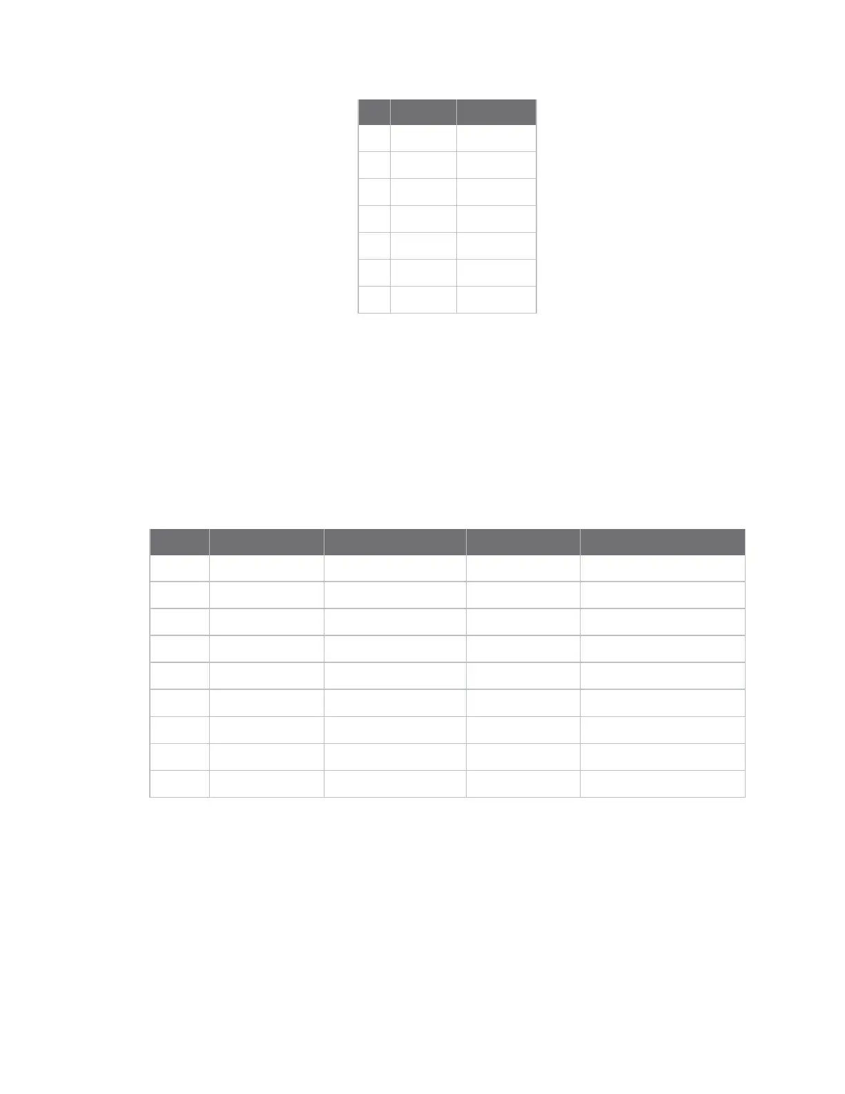
Serial port 1 pins are allocated as shown:
Pin RS232 Function RS232 Default RS485 Function RS485Default
1 - - CTS- -
2 RXD GPIO4_28 RX+ GPIO4_28
3 TXD GPIO4_29 TX+ GPIO4_29
4 - - RTS- -
5 GND - GND -
6 - - RX- -
7 RTS# GPIO4_30 RTS+ GPIO4_30
8 CTS# GPIO4_31 CTS+ GPIO4_31
9 - - TX- -
By default, serial port 1 signals are configured as GPIO signals.
Serial port 3, TTL interface, X19
The serial (UART) port 3 interface is a TTL interface connected to a 2x5 pin, 2.54mm connector, X19.
The connector supports only TTL level signals.
The serial port 3 interface is connected to i.MX51 UART port 3.
Serial port 3 pins are allocated as shown: