About the development board UART interface
ConnectCore for i.MX51 Hardware Reference Manual
115
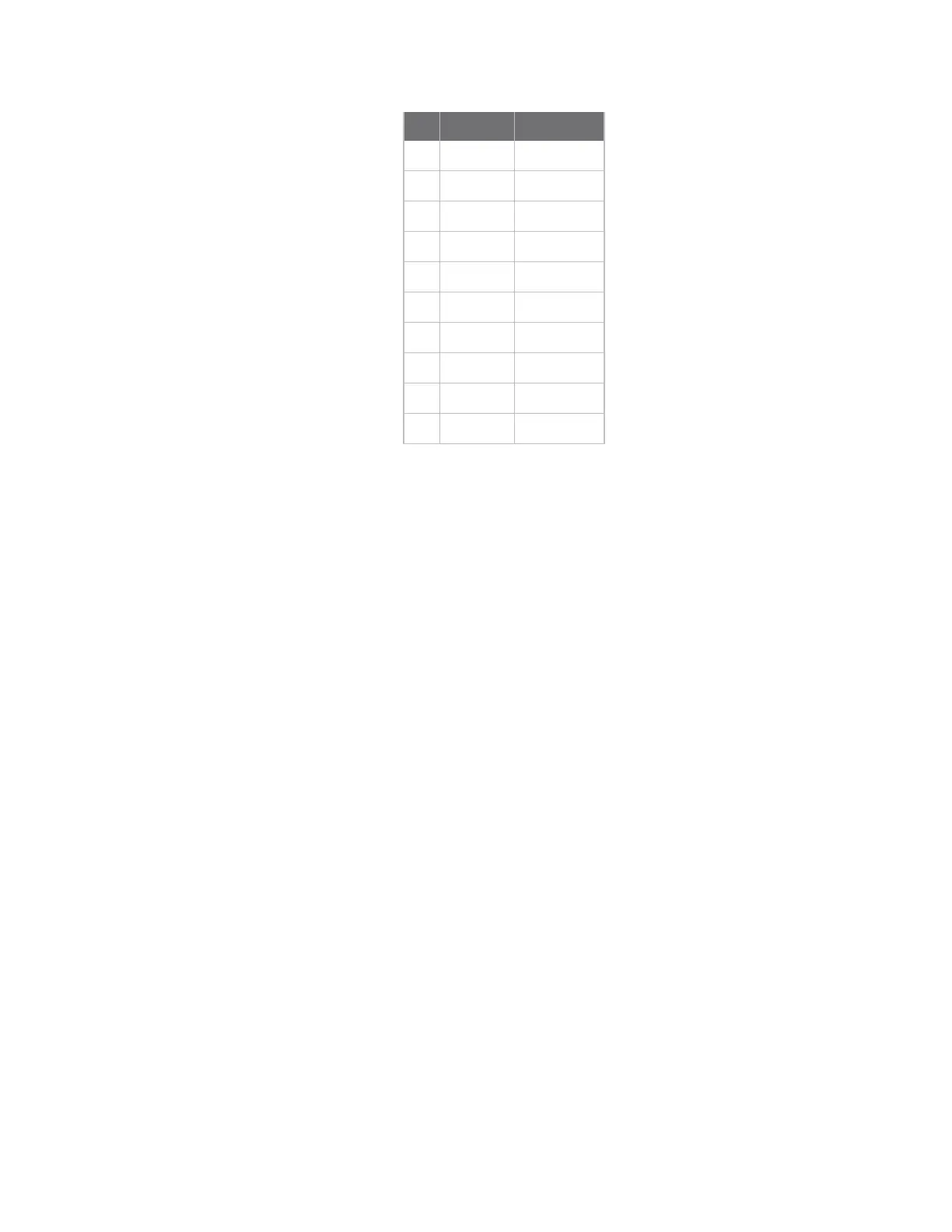
Pin Function Defaults to
1 NC -
2 NC -
3 RXD GPIO1_22
4 RTS# KEY_COL4
5 TXD GPIO1_23
6 CTS# KEY_COL5
7 NC -
8 NC -
9 GND -
10 +3.3V -
By default, serial port 3 signals are configured to their respective GPIO or KEY_COL signals.
Serial port 3 is connected to the X19 connector and to the XBee module socket. Two jumpers (J30 and
J31) are used in the development board to select the connector where serial port 3 will be available.
Refer to Jumpers for more information.
By default serial port 3 CTS# signal is not connected to X19. A 0Ω resistor, R44, must be manually
populated to connect this signal to the X19 connector.