About the development board Switches and push-buttons
ConnectCore for i.MX51 Hardware Reference Manual
68
The Turn Off event does not directly power off the module. The module is powered off by the
processor's response to this interrupt. The software can configure a user initiated power down, or a
transition to a low power off mode by pressing this power button.
When in Off mode or in low power mode, the module can be powered via the Turn On event generated
by pressing the Power button.
User buttons, S3 and S5
Use the user push-buttons to interact with the applications running on the ConnectCore for i.MX51
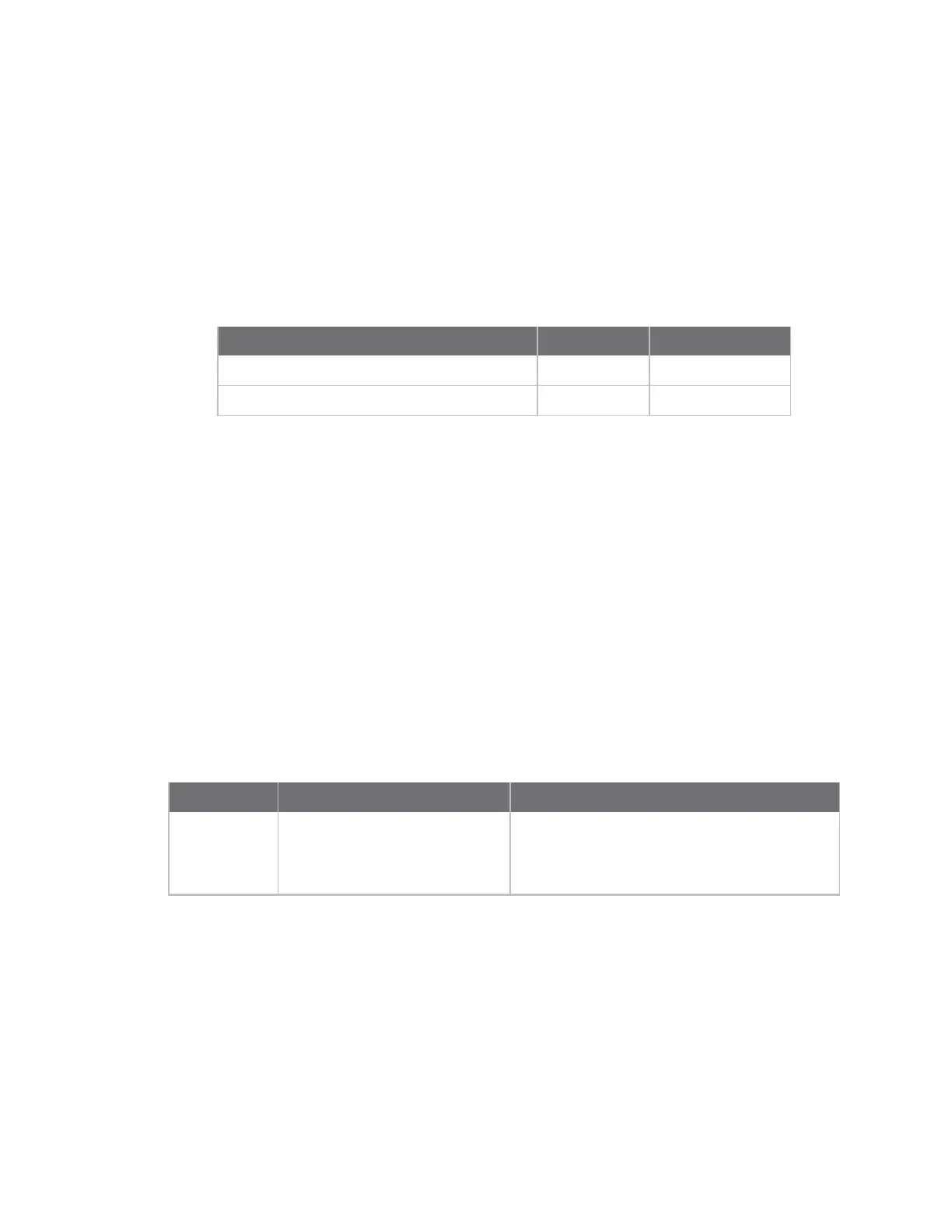
module. Use these module signals to implement the push-buttons:
Signal name
Button GPIO used
DISPB2_SER_DIO/GPIO3_6/USER_KEY1 S3 GPIO3_8
GPIO1_1/SD1_WP#/SPI_MISO/USER_KEY2 S5 GPIO1_1
GPIO3_6 is used in User Button S3 and also in the Digital I/O connector for Digital I/O7.
Ident button, S10
The Ident push-button S10 is associated to the commissioning input of the Digi XBee modules. This
input provides a variety of simple functions to aid in deploying devices in a network. For a deeply
description of this functionality please refer to the Digi XBee modules documentation.
Legend for multi-position switches
Switches S6, S7, S8 and S9 are multi-pin switches. In the description tables for these switches, the
position is designated as S[switch number].[pin number]. For example, position 1 on switch S6 is
specified as S6.1.
UART 1 switch, S6
Use S6 to configure the line interface for serial port 1 MEI:
Switch Pin Function Comments
S6.1 On = RS232 transceiver enabled
RS4xx transceiver disabled
Off = RS232 transceiver disabled
RS4xx transceiver enabled