About the development board SPI interface
ConnectCore for i.MX51 Hardware Reference Manual
112
Interface Chip Select
(*) the SPI chip select signal for the two LCD interfaces is generated with a logic combination of
GPIO4_26 and the touch selection jumper (J20).
The SPI bus is connected to the following interfaces of the ConnectCore for i.MX51 module.
Interface Chip Select
MC13892 Power Management CSPI1_SS0/GPIO4_24
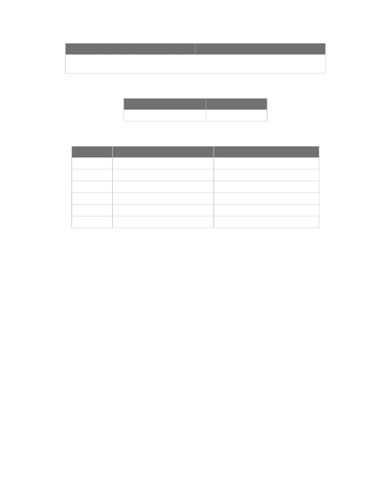
The table below provides the pinout of the SPI header:
Pin Function Defaults to
1 +2.775V
2 SPI_MOSI/GPIO4_22 GPIO4_22
3 SPI_MISO/GPIO4_23 GPIO4_23
4 SPI_SCLK/GPIO4_27 GPIO4_27
5 SPI_SS1/GPIO4_25 GPIO4_25
6 GND
By default, SPI pins are configured as GPIO signals.