28 Scale Link 2 Technical Manual D4204-EN
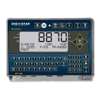
SLC2810 System
• No SLC2810 display
o No power. SL2 powers the SLC2810, so make sure SL2 is getting power.
o Make sure M12 connector fully inserted and tightened to SL2 box.
o Verify SLC2810 cable is not cut or crushed.
o Verify no loose wires inside SLC2810 box.
o Verify SLC harness inside of SL2 box is seated and no loose wires.
o Make sure system voltage is 9 to 16VDC. The SLC2810 remote is only designed for 12V nominal
systems. Higher voltages may damage this display.
• SLC2810 display segments missing, certain keys not working, etc
o Possible failing SLC2810 remote. Contact Topcon service.
TST System
• Weight not displaying on TST
o Low battery condition at SL2. System voltage needs to be above 11 VDC to broadcast weight.
o Incorrect settings on SL2 (OPSTAT, COM port, etc)
o Loose, damaged, or defective cable between SL2 and TST
• Other TST issues
o TST monitor settings or hardware. Refer to TST manuals and troubleshooting.
Other Issues
• Things to check with a volt meter
o There should be 4 blue lights inside SL2. They represent system power, 8V, 5V, and 3.3V circuits.
o System power. Make sure there is at least 11 volts from +VIN to 0V. Data will not broadcast on CAN
or RS232 below 11 volts system power.
o Load cell power. Make sure there is about 8 volts from RED to BLK. If voltage is very low or 0, there
may be a short somewhere in the load cell wiring.
• Communication issues; no serial or CAN input/ output
o Wires switched. RS232 RX/ TX swapped; CAN Hi/ Lo swapped.
o One or more settings is incorrect for the application. You may need a SLC2810 to diagnose and
update these settings.
o There are 3 status lights on board. If red ones are lit or flashing, there is an error of some type.
Green, yellow, or no lights generally indicate basic operation.
• OP1 output has a red light turn on when the output is active at +VIN level.