DSF22 UNIQUE MONITORING TERMINAL
4
INSTALLATION AND SETUP GUIDE
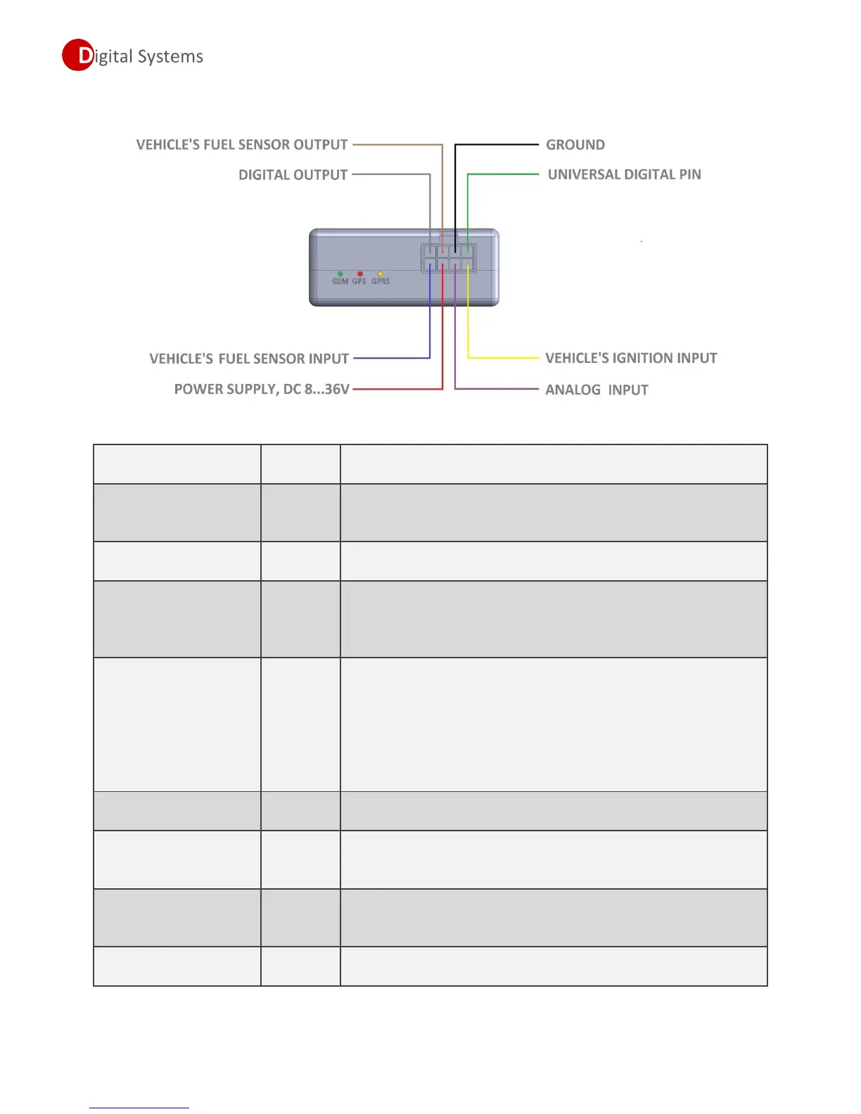
Wiring diagram.
Description of wires.
This wire used to power a GPS/GSM monitoring terminal, must
be connected to positive terminal of vehicle’s battery. Power
supply must be within range 7…36 Volts.
This wire must be connected to negative terminal of vehicle’s
battery or to vehicle’s chassis.
This wire used to monitor a status of vehicle’s ignition, and
switch monitoring terminal from idle to tracking mode. Must be
connected to ignition switch, voltage range for this input must be
within 7…36 Volts (ignition ON state).
This is universal pin, by default it’s configured as digital input,
can be used to monitor a status of electrical equipment in the
vehicle, such as lights, door opening, etc.
Can be configured as digital Open-collector output, max load
500mA. Can be used for remote activation some of vehicle
systems, such as lights, heater, etc.
Open-collector output, max load 500mA. Can be used for remote
activation some of vehicle systems, such as lights, heater, etc.
Vehicle’s fuel sensor
input
Specialized Analog input for vehicle’s standard fuel sensor
connection. See section Connection diagram for standard fuel
sensor.
Vehicle’s fuel sensor
output
Specialized output used for vehicle’s standard fuel sensor
connection. See section Connection diagram for standard fuel
sensor.
Universal Analog input, voltage measurement range 0…30 volts,
resolution 12 bits.