7
© 2012 Directed� All rights reserved�
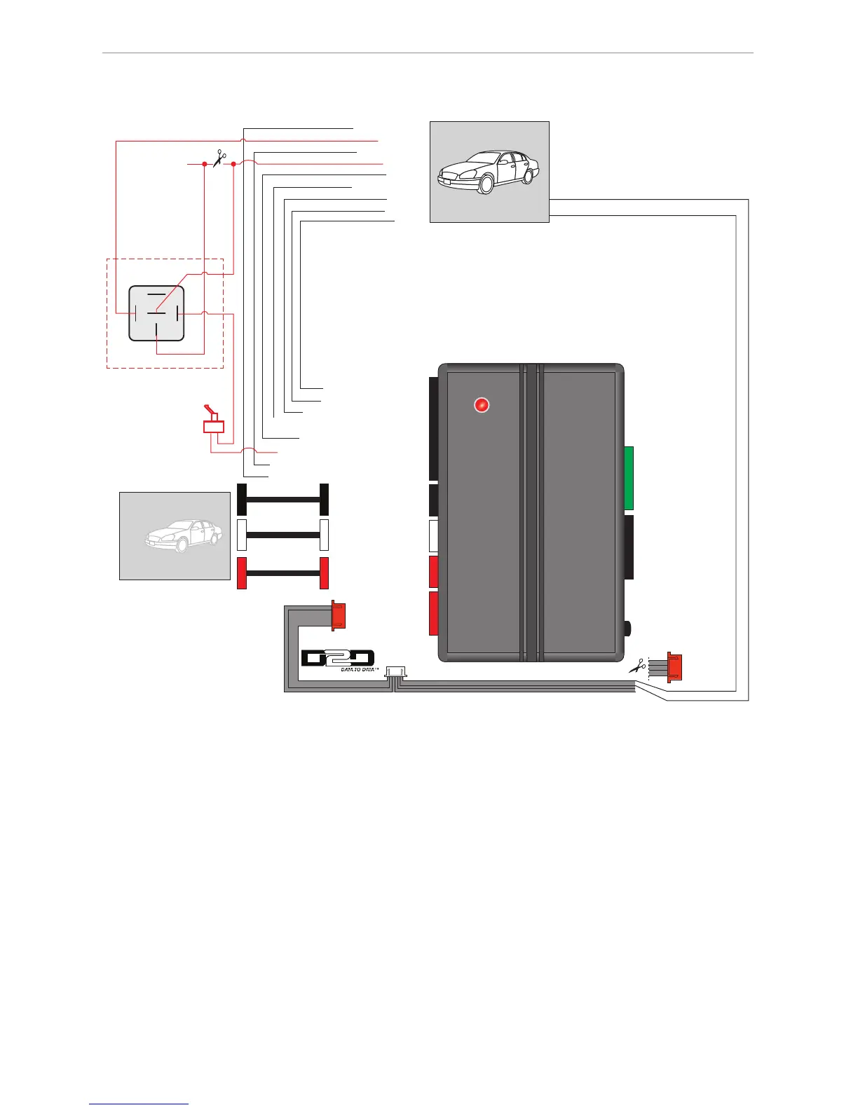
Installation diagram
Type 1 - PKE Standalone
6 Green 6 Black
4 Red2 Black
2 Black
2 Red10 Black
LED
PKE
Prog. Button
(-) Unlock Output: Blue: 2
(-) Lock Output: Green: 1
(+) Door Sense Input: White/Purple: 4**
(-) Starter Kill Output: White/Black: 6
(-) Parking Light Output: White/Pink: 7
(-) Door Sense Input: Blue/White: 10**
(-) Unlock
(-) Lock
(+) Brake
(+) Starter
(+) Ignition
(-) Parking Light
(-) Door Sense**
Antenna (8 feet)
Antenna (18 feet)
86 85
30
87a
87
(+) Brake Input: Purple/Black: 5
(+) Door Sense**
Starter Disable:
This connection is
optional and ad-
ditional parts are
sold separately.
Refer to the
Antenna Location
and Installation Points
section on page 5 for
more information.
(-) Horn Output: Red/White: 3
(-) Horn
This toggle switch will
bypass the starter disable.
(-) Ground: Black: 2
RX: Blue: 1
(+) 12v: Red: 4
D2D Y CABLE
Cut the 4-wire red connector of D2D Y-cable and connect
12v and Ground wires to the corresponding wires of the DIRECTED SmartStart
TM
cable.
Not Used
Ground: Black
(+)12v: Red
Ground: Black
(+)12v: Red
*Sold separately.
**Door sense: The polarity of the door sense in the vehicle will determine which wire to connect
from the PKE to the DIRECTED Remote Starter.
2 White
Optional
Antenna (12 feet)*
(Part# SANT-PKE12)