Systems and Equipment - 90 JT5 Operator’s Manual
Electric Strike System
CMW
®
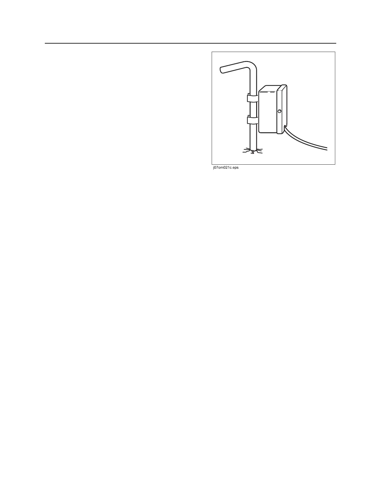
Assemble Voltage Detector
1. Drive voltage stake into ground at least 6’ (2 m)
away from any part of system.
2. Clip voltage limiter to voltage stake.
Test Strike System
If system fails any part of this test, see “ESID Diagnostic Codes” on page 91 on the following page. Do not
drill until test is completed successfully.
1. Turn on drilling unit.
2. ESID control module will perform internal tests which check everything but alarms and strobe.
3. If green OK indicator and electrical power supply indicator lights remain on, press self test button to
perform total test of strike system. During this test:
• All lights should glow.
• Alphanumeric readout should display numbers.
• Alarms and strobes on all connected units should sound.
4. If this test is successful, OK indicator and electrical power supply indicator lights will remain on.
5. Use Electric Strike Simulator to test voltage and current sensors. See page 94.