HARDWARE 3.4 ADJUSTING THE TRIGGER
YOUR LUXE
®
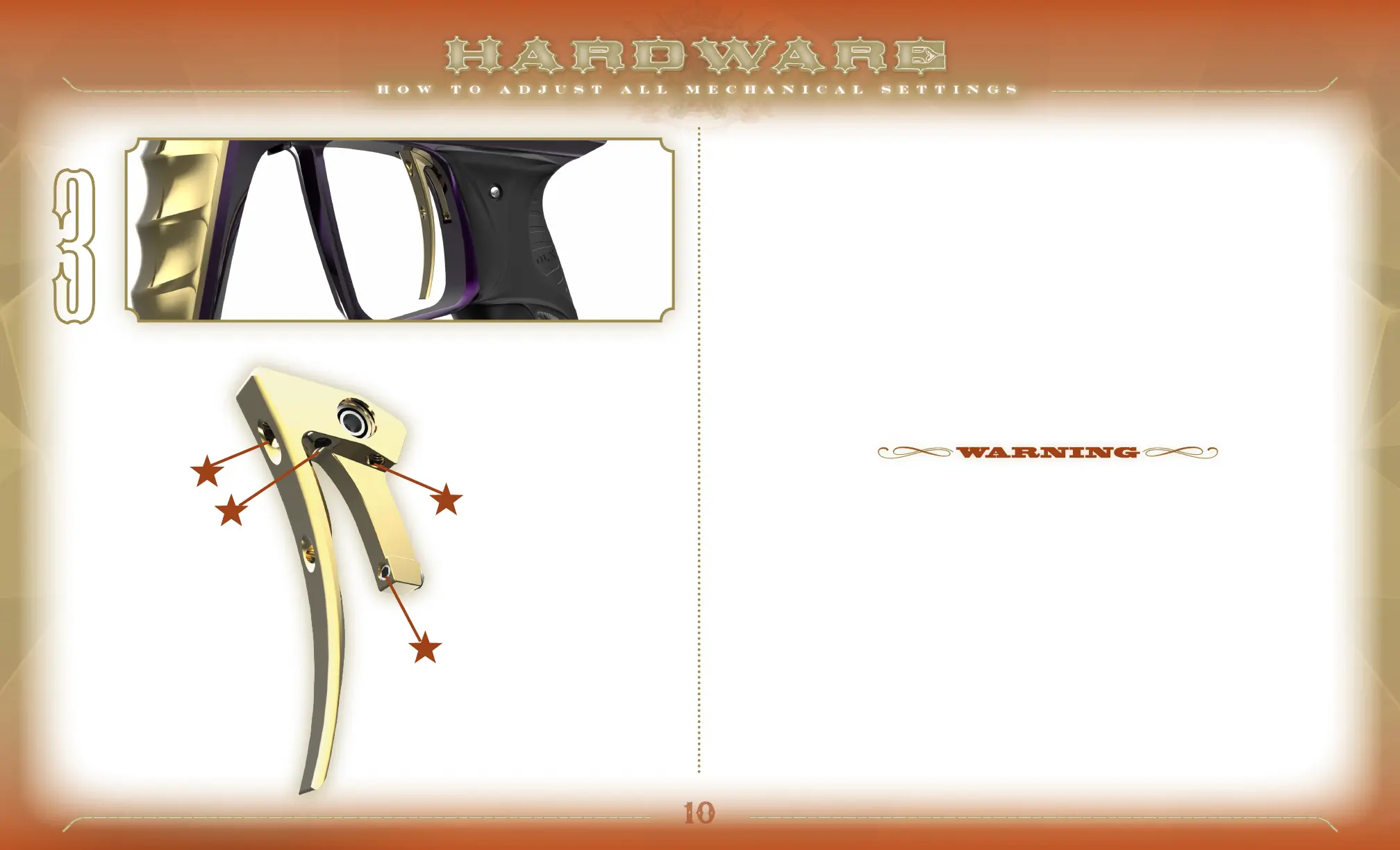
IS EQUIPPED WITH A 4-POINT ADJUSTABLE TRIGGER, providing complete versatility to both the
feel and length of the trigger pull [FIG 3] The Luxe
®
can be adjusted to a super-sensitive hair trigger, though many
players find that a slightly longer, and heavier trigger pull is easier to walk to higher rates of fire. Perform trigger
adjustments while the Luxe® is unloaded and degassed. Luxe
®
Training Mode (see SOFTWARE 4.1) can be used to
determine the effectiveness of changes in trigger adjustment.
PO ST-TR AVEL The post-travel adjustment sets how far back the trigger can travel, affecting the area of the
trigger pull that occurs after the Luxe
®
fires. Turning the adjustment screw clockwise with a 1/16-inch allen wrench
will reduce post-travel, limiting how far back the trigger can swing, while turning counterclockwise will increase it.
The post-travel limit must be set to stop the trigger before it is brought to a stop by the trigger switch.
PRE-TR AV EL The pre-travel adjustment determines how far forward the trigger can swing, affecting the area
of the trigger pull that occurs before the Luxe® fires. Pre-travel is adjusted with an 1/16-inch allen wrench in the
pre-travel adjustment screw. Turn clockwise to reduce pre-travel, and counterclockwise to increase.
ACTIVATION POINT The activation point setting determines the point in the trigger pull at which the
Luxe
®
trigger switch is activated, signaling the marker to fire. As the screw is turned clockwise with a 1/16-
inch allen wrench, it will extend out the back of the trigger, closer to the trigger switch, causing the trigger to
be activated earlier in the trigger pull. Due to the limited space to access this adjustment, use of a ball-end
allen wrench is advised.
USE CAUTION WHEN ADJUSTING THE ACTIVATION POINT AND POST-TRAVEL ADJUSTMENT. WHEN PROPERLY
ADJUSTED, THE TRIGGER SHOULD COME TO A SOLID STOP AGAINST THE POST TRAVEL ADJUSTMENT SCREW. IF IT
COMES TO A SOFTER STOP CAUSED BY THE ACTIVATION POINT ADJUSTMENT SCREW OR REAR OF THE TRIGGER
PRESSING AGAINST THE TRIGGER SWITCH, THEN TRIGGER SWITCH AND OR CIRCUIT BOARD DAMAGE MAY RESULT
FROM RAPID OR HARD PULLS ON THE TRIGGER.
TRIGGER RESISTANCE Trigger resistance, or the weight of the trigger pull may be adjusted with a 1/16-
inch allen wrench in the trigger resistance adjustment screw. Turning clockwise increases pressure on the trigger
return magnet, for increased resistance, while turning counterclockwise decreases pressure on the trigger.
1 P O S T-T R AV E L
2 PR E-T R AV EL
3 ACTIVATION POINT
4 RE S IS TA NCE
1
4
3
2
FIG.