Digital Monitoring Products, Inc. | Troubleshooting Guide 9
TROUBLESHOOTING THE 866 STYLE W NOTIFICATION MODULE
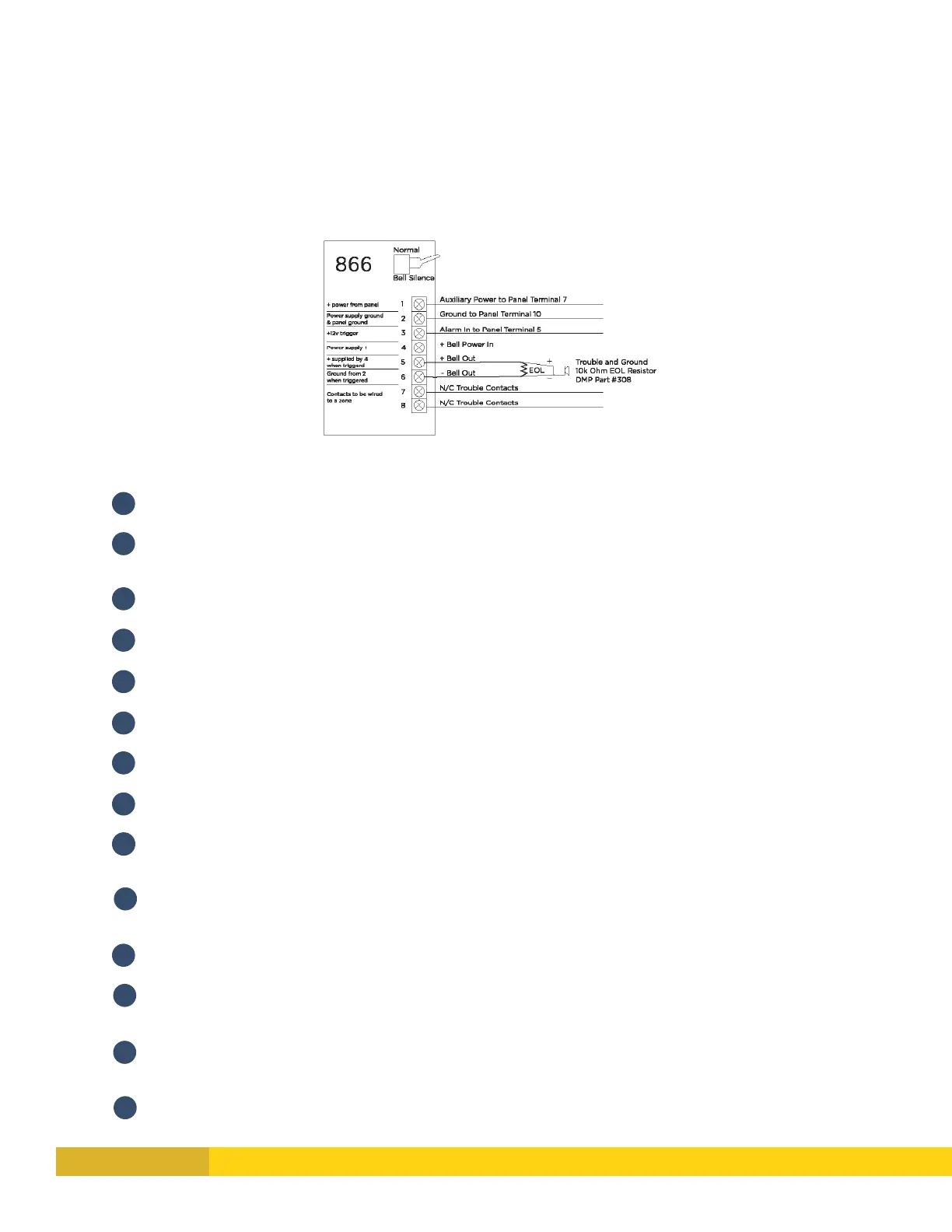
The 866 uses the panel’s bell circuit to switch power from an external power source to sirens and other notification
devices� It also supervises the connection to the external power source� The most important thing to know with the 866
is which wires connect to the panel versus which wires connect to the power source�
HOW THE 866 WORKS
1 & 2 power the 866 module� The positive trigger on terminal 3 tells 2 & 4 to send voltage to 5 & 6�
HOW TO TROUBLESHOOT AN 866
1
Metering 1 & 2 should show +12V (or +24V if using a 24V power supply)�
2
If no voltage between 1 & 2, make sure the ground and power are coming from the same source (panel or
power supply)�
3
Metering 2 & 3 should show approximately 0 to 1�2V when normal�
4
Metering 2 & 3 should show +12V when tripped�
5
If using Horn Strobes, steady voltage on terminal 3 is required�
6
If they say the 866 should be tripping, they must have +12V on 2&3 to be triggering it�
7
Metering 2 & 4 should show +12V (or +24V)�
8
If power is coming from the panel bell, you will have 0-1�2V until the bell trips�
9
If no voltage on 2 & 4, you won’t have any power to power the bell output� Make sure the ground and
power are coming from the same panel or power supply�
10
Metering 5 & 6 should show negative volts while the 866 is normal (-6V or -12V) then +12V (or +24V)
when triggered�
11
If the bell isn’t tripping, strap out 5 & 6 with a 10K resistor and meter terminals 5 & 6 while tripped�
12
If you are experiencing a delay when sounding, make sure the bell silence switch is normal and a 10K
resistor is installed on terminals 5 & 6�
13
Metering 7 & 8 for continuity should show continuity while normal� If there is no 10K resistor on 5 & 6, this
contact will show open� Remember, this is a contact, not a zone�
14
If the Normally Closed contact on 7 & 8 is open make sure the silence switch is normal and that there is a
10K on 5 & 6�