DOD Technologies, INC • 675 Industrial Dr. Bldg. A • Cary, IL 60013 • Phone (815) 788-5200 • Fax (815) 788-5300
Innovative Life Safety Systems & Services
Both 24VDC supplies on pump panel
Greater than 24.6 – 24.8 VDC
12VDC supply on pump panel
5VDC supply on pump panel
24VDC in control box for PC
24VDC in control box for I/O
5VDC in control box for flow system
5VDC supply for optic blocks
*All power supplies can be adjusted with potentiometer
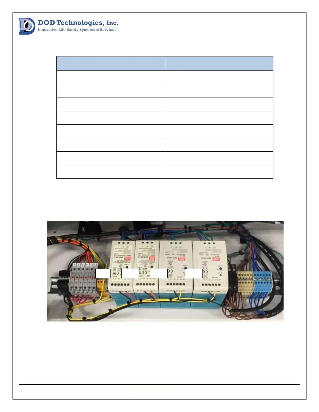
All power supply voltages should be measured from the pump panel (image below) to begin the voltage
verification test and voltages should be adjusted with the potentiometer if outside of the factory
specification.
In the Control Box there is a row of terminal blocks mounted on the rear panel (see image below). The
supply voltage for the PC and monitor can be measured at the yellow terminal block. The 12VDC supply
can be measured at the orange terminal block and the 5VDC for the flow system can be measured at the
red terminal block. The DC voltage verification should be done at the yellow terminal blocks mounted on