4302-067-G-2-21
13
2.3 Entrapment Protection Continued
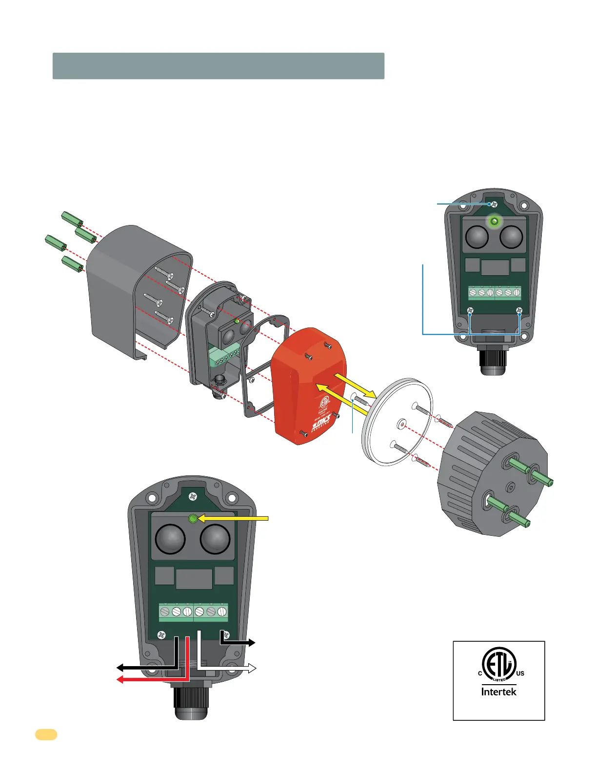
DoorKing 8080-057 Retro-Reflective Photocell Type B-1
Installation
Adjustment
This retro-reflective photocell (UL 325 Type B-1) complies with the 2018 UL 325 standards. It must be wired to the control box using the
photocell’s NORMALLY OPEN input so the control box can monitor the photocell. The photocell is powered by 24 VAC from the #3 circuit
board terminal if desired. The relay output is rated for 1 Amp @ 24 VDC and 1 Amp @ 120 VAC maximum.
It MUST be mounted vertically as shown and not horizontally to protect it from the weather. The green LED will remain lit when the reflector is
aligned correctly with the photocell. The photocell has a max sensing range of 35 ft.
Retro-Reflective Photocell
Assembly
Beam
Max Sensing Range 35 ft
Plastic
Sleeve
Anchors
Longer Roundhead
Screws x4
Shorter
Roundhead
Screw x1
Beam
reflects
b
ack
to photocell
and lights
green LED
Wiring Photocell
Mount photocell vertically and
wire BEFORE mounting reflector.
See previous page for locations of
your chosen gate operator type.
Photocell can be
powered by the
circuit board if
desired or use a
separate UL listed
power supply.
DO NOT connect
power supply to a
receptacle controlled
by a ON/OFF switch.
Note: Relay contacts are labeled with power applied.
Reflector
Assembly
Flathead
Screws
Plastic
Sleeve
Anchors
Position reflector directly across from mounted photocell.
Green LED on photocell will remain lit when reflector is in
correct position. Permanently mount reflector making sure
LED remains lit. “Fine tune” photocell alignment if necessary,
see above.
Weather
Protection
Cover
S6 AC10-25V
DC12-30V
NO NC COM
S6 AC10-25V
DC12-30V
NO NC COM
Beam Sensors
Green LED
remains ON
when reflector
is properly
aligned.
To Com
To 24 VAC
After photocell has been
mounted, spring mounted beam
sensors can be precisely
adjusted “Fine tuned” using the
3 screws to help keep the
GREEN LED ON if necessary.
Power Relay
Non-Removable Terminals
Flathead
Screws
Green LED
UL 325 Compliant
4008099
To #1 Open Beam OR #2 Close Beam
(depending on mounting location, see previous page)
Relay to UL 325 Terminal:
To GND
Power to
Circuit Baord
Terminal #1 & #3