4302-067-G-2-21
24
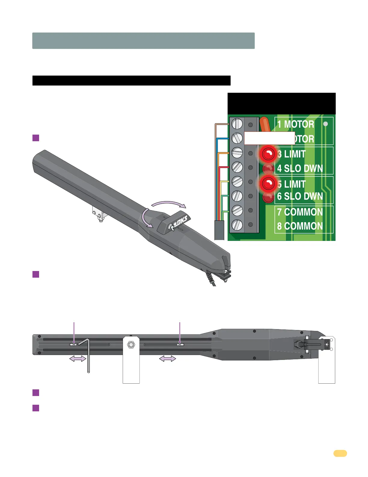
3.3 Limit Sensors Adjustment Continued
6006 Limit Sensors ONLY
Manually move the gate to the desired open or closed position.
Loosen set screw and slowly slide the limit assembly.
SLOW DOWN LED will light first, continue sliding until the corresponding
LIMIT LED on the circuit board lights up. Tighten screw.
Manually move the gate to other position. Repeat process with the other
limit assembly.
Manually unlock handle with key and rotate it 90°.
A
B
C
D
Power to the circuit board must be ON when adjusting the limit sensors.
Adjust the secondary actuator limit sensors if dual actuators have been installed. DIP-switch SW 1, switch 2 controls
secondary actuator opening direction. DIP-switch SW 1, switch 7 MUST be ON when using dual actuators (See page 20).
Rotate handle back 90° and re-lock it. Test the gate stopping positions. Re-adjust if necessary.
IMPORTANT: The operator MUST OPEN GATE upon initial power up and OPEN command.
If the operator closes gate after giving first open command, shut off power and reverse DIP-switch SW1, switch 1 setting
otherwise operator will NOT function correctly.
Set Screw
Hex Wrench
Bottom View
Set Screw
Note: 3 and 5 limit LEDs can be
Open or Close limits depending
on SW 1, switch 1 and 2 settings
(See page 19).
5 LIMIT 3 LIMIT
Limit LEDs
If factory wired jumpers are installed on
operator terminals, they must be
removed or operators will not function.
7-Wire
Operator
Cable
Handle
90°
Note: Handle can
be rotated 180° and
locked facing either
side of operator for
easy key access.
Rotate handle 90°
in either direction to
release carriage.