4302-067-G-2-21
25
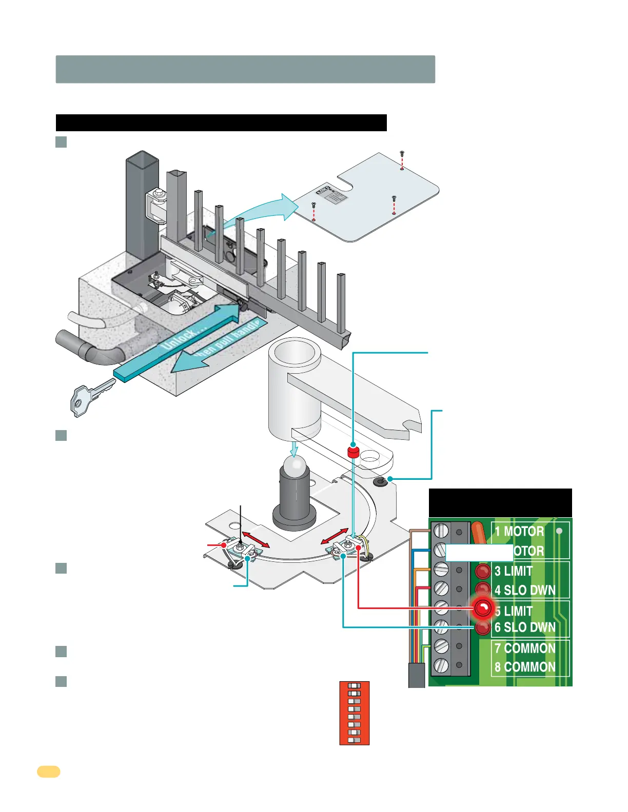
3.3 Limit Sensors Adjustment Continued
6400 Limit Sensors ONLY
7-Wire
Operator Cable
Cover Plate
C
L
A
S
S
C
E
R
T
I
F
I
E
D
T
O
C
A
N
/
C
SA
C
2
2
.
2
N
O
.
2
47
C
O
N
F
O
R
M
S
T
O
A
N
S
I/
U
L
-
3
2
5
VE
H
I
C
U
L
A
R
G
A
T
E
O
P
E
R
A
T
O
R
HP
5
3
3
8
2
M
O
DE
L
S
E
R
I
A
L
V
O
L
T
S
P
H
A
SE
A
M
P
S
6
0
H
z
M
AX
GA
T
E
L
O
A
D
D
o
o
r
K
i
n
g
,
I
n
c
.
,
I
n
g
l
e
wo
o
d
,
C
A
6 Slow Down
4 Slow Down
5 Limit
Limit Sensor Wire Color LEDs
Re-lock release handle
with key and test the gate
stopping positions.
Re-adjust if necessary.
Adjust the Secondary operator limit sensors if
dual operators have been installed. DIP-switch
SW 1, switch 2 controls secondary operator
opening direction. DIP-switch SW 1, switch 7
MUST be ON when using dual operators.
(See page 21)
Re-install the operator cover plate.
With operator cover plate removed, un-lock release handle and pull handle to release gate.
A
B
C
D
E
Limit
Nut
Note: 3 and 5 limit LEDs can be
Open or Close limits depending
on DIP-switch SW 1, switch 1
and 2 settings. (See page 21)
Embedded magnet on underside
activates limit sensors when it
passes over them.
Limit assembly positions
may vary depending on the
operator’s drive motor
orientation. Limit sensor wire
color LEDs remain the same.
3 Limit
SW 1
Primary Operator
Secondary Operator
Single or Dual Operators
1
ON
2 3 4 5 6 7 8
3 Limit LED - Gray/White
4 Slo Dwn LED - Purple/White
5 Limit LED - Yellow/White
6 Slo Dwn LED - Brown/White
Power to the circuit board must be ON when adjusting the limit sensors.
Limit LEDs
Unlock...
...then pull handle
Limit
Assembly
Manually move the gate to the desired open
or closed position. Loosen limit nut and
slowly slide the limit assembly until the
corresponding LIMIT LED on the circuit board
lights up and tighten nut.
Manually move the gate to other
position. Repeat process with
the other limit assembly.
IMPORTANT: The operator MUST OPEN GATE
upon initial power up and OPEN command.
If the operator closes gate after giving first open
command, shut off power and reverse DIP-switch
SW1, switch 1 setting otherwise operator will NOT
function correctly.
If factory wired jumpers are installed on
operator terminals, they must be
removed or operators will not function.