4302-067-G-2-21
20
ON DIP
1234
F2
F1
F0
F0
S1
S2
A
B
CH1
SW2
SW1
LOOP 1
CH1
POWER
9416-010
1 Channel
ON DIP
1234
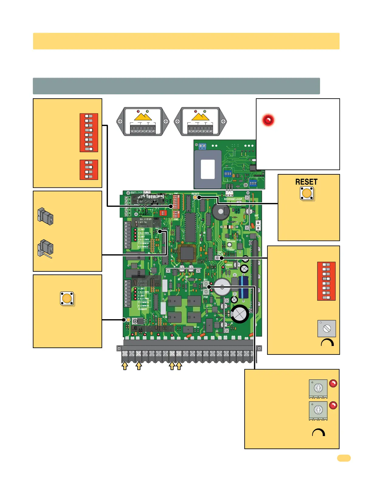
3.1 4302 Circuit Board Description and Adjustments
SECTION 3 - ADJUSTMENTS
The switch settings and adjustments in this section should be made after your installation and wiring to the operator(s) is
complete. Whenever any programming or switch setting on the control board are changed, press the reset button for new
settings to take effect.
• Auto-close timer
(when turned ON)
SW 1, switch 4.
Adjust from 1 second
(full counter-
clockwise) to
approximately 23
seconds (full
clockwise)
Press reset button to
activate changed
control board settings.
Turns OFF activated
alarm (See page 36).
Cycles the operator when
pressed. Will use Auto-Close
timer when turned ON. This
switch WILL NOT function
when there is NO power to
the circuit board (Idle time).
TIME
DELAY
123
Auto-Close Timer
Battery Plug
See page 18.
Set DIP-switches
on the circuit
board to the
desired setting.
See switch-setting
charts on next 2
pages.
DIP-Switches
Adjust reversing
sensitivity for:
PRIMARY (single) and
SECONDARY (dual)
operators. See page 26.
SEC
PRM
Min Max
Sensitivity
Inherent
Reverse Sensors
OB
CB
Close
Beam
Open
Beam
GND
GND
SW1
1
ON
2
1476-010
1 2 3 45
6
7
89
10 11 12
13
14 15
16 17 18 19
20
4302-018
SW 1
1
ON
2 3 4 5 6 7 8
SW 1
1
ON
2 3 4 5 6 7 8
SW 2
1
ON
2 3 4
Self test mode is for
bench checks ONLY.
The operator will
continually cycle the
gate.
The jumper must be
set at normal mode
to function.
Self Test
Mode
Normal
Mode
Self Test
SECONDARY
Operator
See page 11.
PRIMARY
Operator
See page 11.
Input LEDs
Circuit Board Terminal
Limit LEDs
See pages 23-25.
How LEDs Function
Illuminated LEDs Indicates that
low voltage power is being
applied to the circuit board.
Input LEDs should be OFF and will only
illuminate when the input wired to the
corresponding main terminal is activated.
Limit LEDs will only illuminate when the
respective limit sensor has been activated.
Used to wire external
reverse loop detector.
See page 15.
Used to power
8080-057 photocell.
See page 12.
“Optional” External Loop Detectors See 15 and 17.
Diablo
Controls, Inc.
Stuck in traffic for over 37 years!
NC COM
RELAY
10 to 30 Volts
AC or DC
POWER DETECT
DSP-7
POWER LOOP
COM
+
NO
REMOVE
CONNECTOR
TO RESET
Diablo
Controls, Inc.
Stuck in traffic for over 37 years!
NC COM
RELAY
10 to 30 Volts
AC or DC
POWER DETECT
DSP-7
POWER LOOP
COM
+
NO
REMOVE
CONNECTOR
TO RESET
FULL
OPEN
FULL
OPEN
Limit LEDs
See pages 23-25.
UL 325 Terminal
See page 12.
“Optional” DKS
Plug-In Loop
Detector
See page 16.
DO NOT USE
EXIT LOOP PORT