4302-067-G-2-21
16
ON DIP
O
12345678
C
F2
F1
F2
F1
F0
F0
F0
F0
S1
S2
A
B
S1
S2
A
B
CH1 CH2
LOOP 2
LOOP 2
OUTPUT
LOOP 1
NC NO
CH1 CH2
POWER
9415-010
2 Channel
SW2
SW1
ON DIP
F2
F1
F0
F0
S1
S2
A
B
CH1
SW2
SW1
LOOP 1
CH1
POWER
9416-010
1 Channel
ON DIP
1234
Reverse
Reverse
Automatic Exit
External Loop
detector ONLY
(See next page.)
Secure Side
Inside Propert
y
Non-Secure
Side
Outside Property
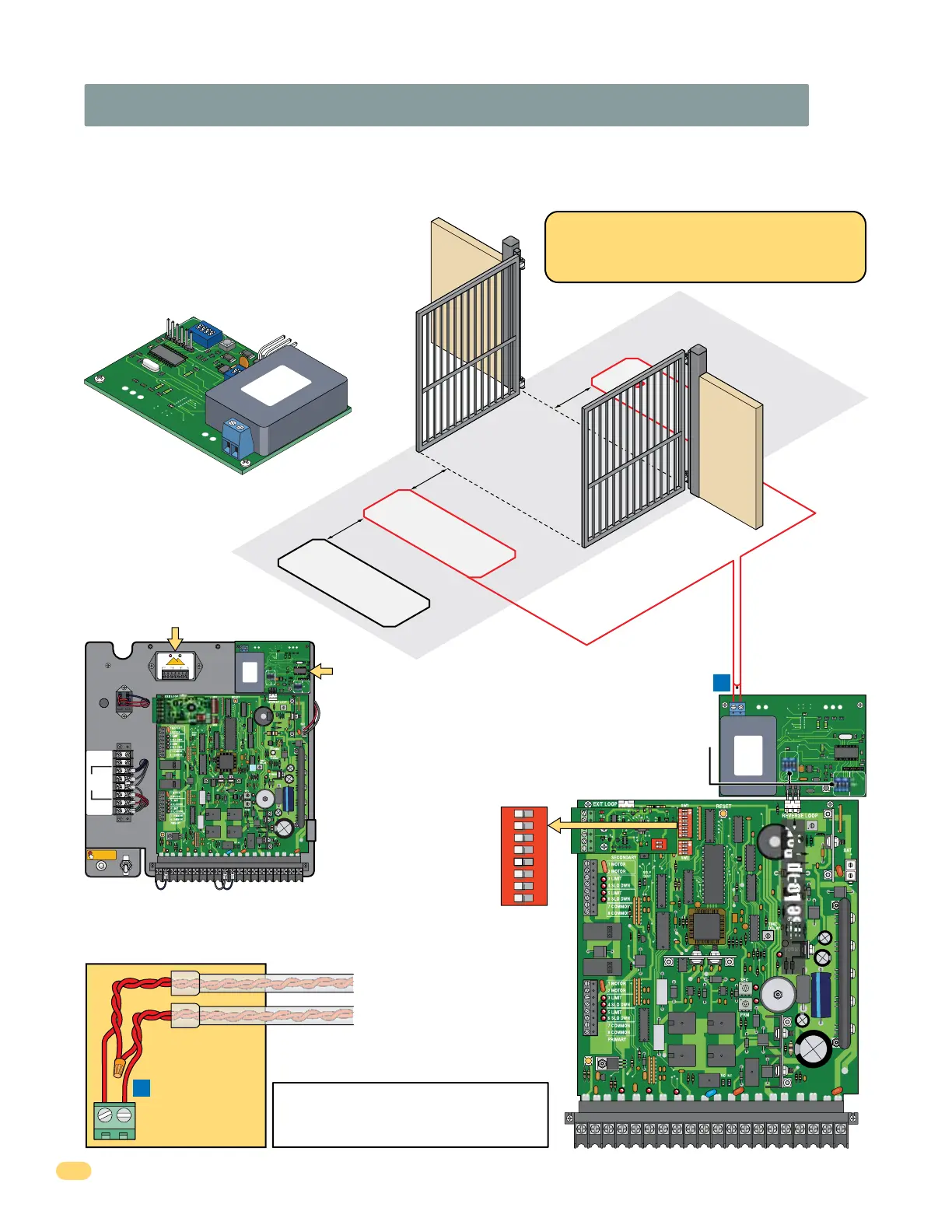
2.5 DKS Plug-In Loop Detector (Reverse Loops ONLY)
Using a DKS Plug-In loop detector for the
reverse loops instead of a external loop
detector will allow less current draw during
“Idle Time” saving battery life.
Reverse Loops
Reverse loops prevent the gate from closing on a
vehicle in or near the gate’s swing pathway.
12345
6
7
89
10 11 12
13
14 15
16 17 18 19
20
To help protect the operator from accidentally closing on vehicles in the gate’s path, DoorKing highly recommends that loops
and loop detectors are used. A loop detection system will sense a vehicle like a metal detector and send a signal to the gate
operator preventing the gate from automatically opening or closing on a vehicle when it is in the gate’s path. DoorKing recom-
mends that a licensed installer perform this work.
Reverse loop
lead-in wires are
twisted approx.
6 twists per foot
and are wired in
series.
A
A
LOOP 1
PVC conduit to
Control box.
Single
Channel
4302-018
DIP-Switch Settings
FULL
OPEN
OB
CB
Close
Beam
Open
Beam
GND
GND
SW1
1
ON
2
1476-010
DoorKing offers a free “Loop and Loop-Detectors
Information Manual” PDF located at Doorking’s
web site for more information. www.doorking.com
4 Ft. min. to avoid gate
movement interference.
4 Ft. min. to avoid gate
movement interference.
4 Ft
. min. to avoi
d
reverse loop interference.
Shadow Loop Note:
A shadow loop can
NOT be wired to the
solar control box.
Type of wiring to be used on ALL external devices:
A) Type CL2, CL2P, CL2R, or CL2X.
B) Other cable with equivalent or better electrical,
mechanical, and flammability ratings.
SW 1
1
ON
2 3 4 5 6 7 8
SW 1, switch 5
is OFF.
Gate will
reverse when
obstruction is
encountered.
DO NOT USE
EXIT LOOP PORT
Reverse Loop Port
DoorKing Plug-In
Low Current Draw
Loop Detector
9416-010
Note: See loop detector
instruction sheet to set
DIP-switches on detector.
F2
F1
F
0
F0
S1
S2
A
B
CH
1
SW2
SW
1
LO
OP
1
CH
1
CH
1
PO
WE
R
ON
DI
P
12
34
O
N
DI
P
1234
9
416-010
1 Cha
nne
l
ON DIP
1234
F2
F1
F0
F0
S1
S2
A
B
CH1
SW2
LOOP 1
CH1
POWER
9416-010
1 Channel
ON DIP
1 2 3 4 5 6 7 8 9 1011121314151617181920
ON
OFF
PUSH TO OPERATE
technician use only
Solar NEG
Solar POS
24 V POS
24 V NEG
Relay COM
Relay N.O.
Full Open
Not Used
Not Used
B
FULL
OPEN
OB
CB
Close
Beam
Open
Beam
GND
GND
SW1
1
ON
2
1476-010
Diablo
Controls, Inc.
Stuck in traffic for over 37 years!
NC COM
RELAY
10 to 30 Volts
AC or DC
POWER DETECT
DSP-7
POWER LOOP
COM
+
NO
REMOVE
CONNECTOR
TO RESET
4302-018
External Exit
Loop detector
mounting position
(See next page)
Plug-In Reverse
Loop detector
mounting
position