4302-067-G-2-21
19
1 2 3 4 5 6 7 8 9 1011 1213141516171819 20
ON
OFF
PUSH TO OPERATE
technician use only
Solar NEG
Solar POS
24 V POS
24 V NEG
Relay COM
Relay N.O.
Full Open
Not Used
Not Used
B
Circuit Board Terminal
OB
CB
Close
Beam
Open
Beam
GND
GND
SW1
1
ON
2
1476-010
US
te
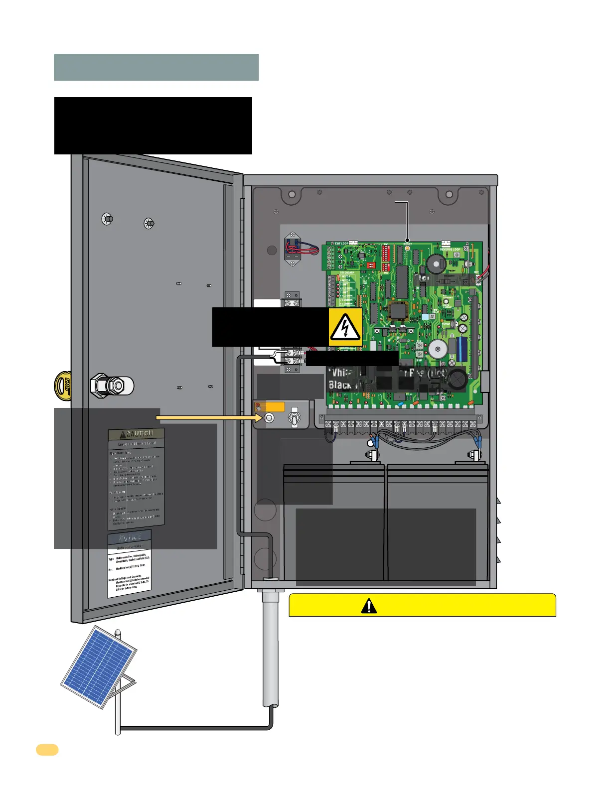
Solar Power Input Conduit
24 Volt Solar Panel Wire
2.8 Solar Panel Wiring
ONLY Use (1) One 24 Volt Solar Panel!
The 24 volt - 10 watt or 20 watt solar panel must be correctly
installed for the system to function correctly. See Section 1 in this
manual for more information about concerns, considerations and
recommendations for proper solar panel positioning and mounting.
Reset Button:
• Resets Circuit Board
• Shuts OFF Alarm
Power
Management
Relay
Battery Plug
To Test Operator:
After all power has been connected,
activate the operator by pressing the
“Push to Operate” button. This button
will use the Auto-Close timer if turned
ON (SW 1, switch 4 ON).
DO NOT cycle gate operator before
DIP-switches and limit sensors have
been adjusted, damage could occur to
gate and operator (See pages 23-25 to
adjust DIP-switches and limit sensors).
DO NOT Connect a
Plug-In Transformer
to the Power Terminals
Power Terminal
ON - Normal operation
OFF - Disconnects
battery power from
circuit board. Solar
panel will continue to
charge batteries.
Power Switch
DANGER of ELECTRIC SHOCK!!
Keep sunlight OFF solar
panel while connecting.
How the system’s 24 volt power is managed: When the
system is NOT in use (idle time), the power management relay will shut
down power to the circuit board. Power will continue at the Full Open -
Power Terminal, keeping the overall power drain of the system to a
minimum during idle time. When an access control device - transmitter,
key switch, exit loop or safety opening device is activated while the
system is idle, the power management relay powers up the circuit board
to open the gate.
DO NOT connect 12 Volt solar panel. Damage WILL occur!!
DO NOT connect larger volt solar panel. Damage WILL occur!!
DO NOT connect 2 or more solar panels. Damage WILL occur!!
Solar Control Box Requirements:
• (1) ONE 24 Volt 10 Watt Solar Panel (P/N 2000-077)
for 18 Amp/Hr Batteries. DO NOT USE 10 watt panel
with the 35 Amp/Hr batteries.
• (1) ONE 24 Volt 20 Watt Solar Panel (P/N 2000-076)
for 35 Amp/Hr Batteries. DO NOT USE 20 watt panel
with the 18 Amp/Hr batteries.
CAUTION
White wire to Solar Pos (Hot).
Black wire to Solar Neg (Neutral).
External Entrapment Protection must be provided for
the gate system where the risk of entrapment or
obstruction exists. The operator will not run without
one or more monitored type B1 or B2 entrapment
protection devices in EACH entrapment area.
4302-018