4302-067-G-2-21
12
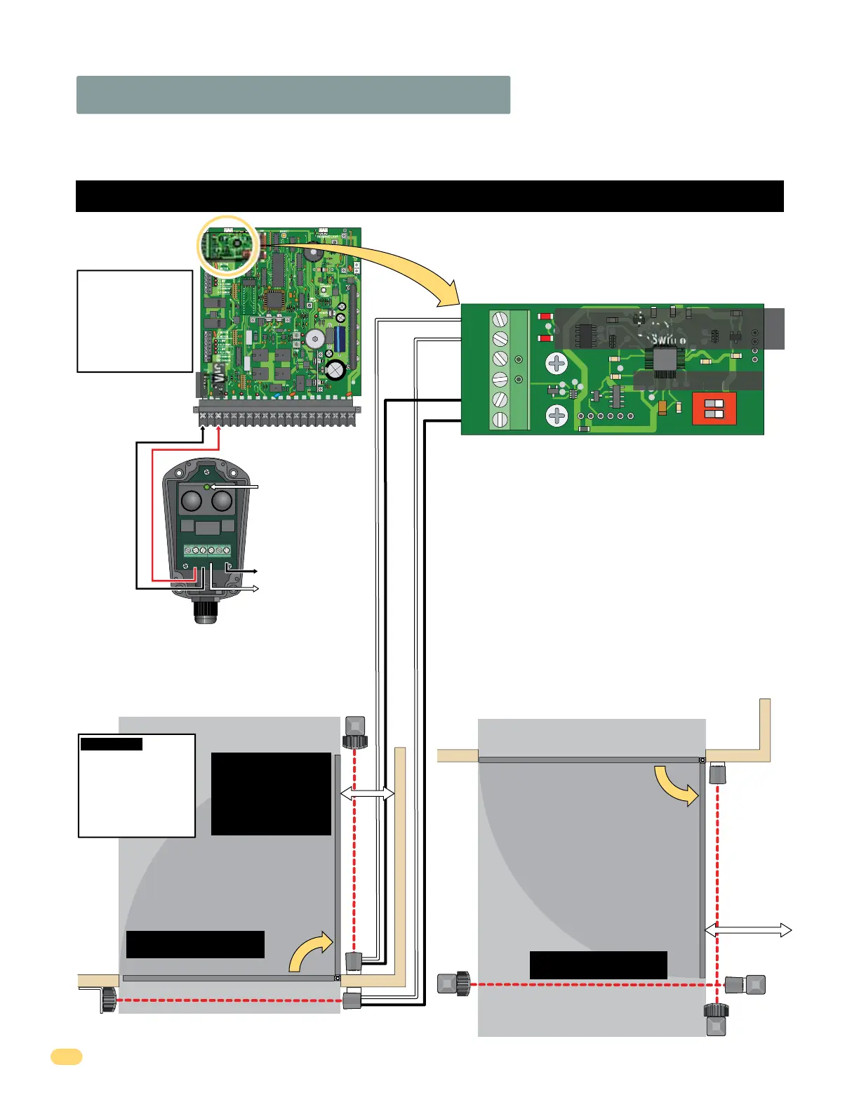
2.3 Entrapment Protection Wiring
OPEN/CLOSE Edge/Beam UL 325 DIP-Switch 1 ON:
OPENING: Obstructed open-direction device will Reverse the gate to the
CLOSE position.
CLOSE Beam UL 325 DIP-Switch 2 ON:
CLOSING: Obstructed closing-direction photo beam will REVERSE the gate
to the open position and reset timer when ON.
Note: If obstruction occurs again during the closing-direction, Gate will
reverse back to open position and enter a soft shutdown.
UL 325 Terminal
Note: Only 1 monitored Device can be connected to each
input. An OPTIONAL Expansion Kit (sold separately) will
allow connection for additional devices.
CB
OB
Not Used
Not Used
Close
Beam
Open
Beam
GND
GND
SW1
1
ON
2
1476-010
UL 325 DIP-Switch
OPEN/CLOSE Edge/Beam (Switch 1)
CLOSE Beam (Switch 2)
DIP-switches
MUST be turned
ON for each device
wired to terminal.
1
2
5
6
External Entrapment Protection Devices:
In addition to the inherent reversing sensor system, this operator has a UL 325 terminal for the connection of photo sensors-Type B1 and/or
reversing edges-Type B2 entrapment protection required by UL 325 standards. Install these devices where the risk of entrapment or a safety
hazard exists. Installations can vary. ONE DoorKing 8080-057 photocell included, see next page.
Monitored CLOSE Photo Sensor
Monitored OPEN Photo Sensor
OPEN Beam
CLOSE Beam (Typically Used)
Entrapment protection is
RECOMMENDED for this area.
Entrapment protection is
RECOMMENDED for this area.
If the distance between an
entrapment or obstruction
exists less than 16” from
the open gate, then
entrapment protection is
REQUIRED for this area.
ONLY connect monitored devices.
The 6-pin terminal can be unplugged from
circuit board for easy wire connections.
CLOSE Beam
OPEN Beam
Closed Gate
Closed Gate
Open Gate
Open Gate
LED Notes:
LED OFF: appropriate device is connected.
LED ON: device has been activated.
Flashing LED:
Device NOT connected. Not appropriate device.
ONLY if an
entrapment or
obstruction
exists less
than 16” away
from open
gate.
Gate Opening
OUTSIDE Property
Gate Opening
INSIDE Property
IMPORTANT: Monitored
Photo and Edge sensors
must be end-of-line
resistive types. See
specific manufacturer's
wiring manual for more
information.
Entrapment Protection must be provided for the gate system where the risk of entrapment or obstruction exists. The operator will NOT
run without ONE or more monitored type B1 or B2 external entrapment protection devices installed in each entrapment area.
2 4 5 6 7 8 9 1011 12131415 1617 18192013
4302-018
CB
OB
Close
Beam
Open
Beam
GND
GND
SW1
1
ON
2
1476-010
FIRE
1475-010
1
2
3
4
5
6
Type of wiring to be used
on ALL external devices:
A) Type CL2, CL2P, CL2R,
or CL2X.
B) Other cable with
equivalent or better
electrical, mechanical,
and flammability ratings.
Circuit Board
Terminal
DoorKing
Photo Sensor
8080-057
(Included, see next page)
S6 AC10-25V
DC12-30V
NO NC COM
To #1 Open Beam OR
#2 Close Beam
(depending on mounting
location, see below)
Green LED remains ON
when reflector
is properly aligned.
Power to
Circuit
Board
Terminal
#1 & #3
Relay to UL 325 Terminal:
Power Relay
To GND
Com
24 VAC