4302-067-G-2-21
22
OFF
OFF
ON
Auto-Close
Timer
3
4
Leave in the OFF position.
Auto-close timer is OFF. Manual input required to close gate.
Auto-close timer is ON. Adjustable from 1-23 seconds.
Not Used
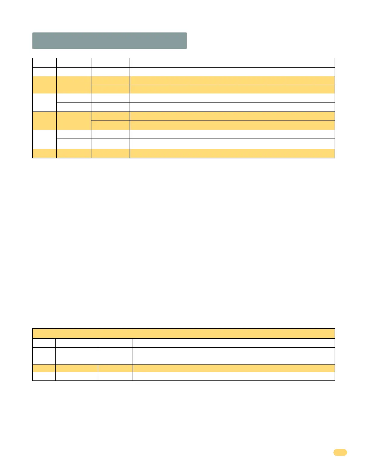
3.2 DIP-Switches Continued
Switch Function Setting Description
SW 2 - Bottom 4 Switches
SW 1 Switch Definitions:
SW 2 Switch Definitions:
SW 2-Switch 1 and 2: These work in conjunction with each other and will activate the relay on the circuit board ONLY when the
gate is not closed. Switch 1 MUST be OFF and Switch 2 MUST be ON. DO NOT use any other switch combinations.
SW 2-Switch 3: Not used, leave in the OFF position.
SW 2-Switch 4: Spare switch. Leave in OFF position.
1-OFF 2-ON Circuit board relay activates when the gate is NOT closed.
Spare
Leave in the OFF position.
OFF
Leave in the OFF position.OFF
Relay
Operation
1 and 2
3
4
Not Used
SW 1-Switch 1: PRIMARY motor direction switch - Must OPEN the primary gate upon initial AC power up and open command. If
the open command begins to close the primary gate, turn AC power off and reverse this switch.
SW 1-Switch 2: SECONDARY motor direction switch - Must OPEN the secondary gate upon initial AC power up and open
command. If the open command begins to close the secondary gate, turn AC power off and reverse this switch.
SW 1-Switch 3: Not used, leave in the OFF position.
SW 1-Switch 4:
Turns the auto-close timer on or off. Maximum time that the close timer can be set for is approximately 23 secs.
SW 1-Switch 5: OFF setting is Standard Reverse for a CLOSING gate. An input to terminal #8 (e.g.: N.O.-photo beam gets
obstructed, NOT entrapment protection) AND/OR reverse loops get activated will stop and reverse the gate back to the full open
position. If the auto-close timer is ON, when gate reaches the open position, timer will not close the gate. Another input
command is needed to reset and close the gate. DO Not use the ON setting.
SW 1-Switch 6: When the gate overlap is OFF, the DUAL gate operators will start the open and close cycles at the same time.
This is the normal setting for a SINGLE gate operator.
Turning the gate overlap ON when using dual gate operators will cause the secondary operator to start the OPEN cycle 1-2
seconds before the primary operator. The primary operator will start the CLOSE cycle 1-2 seconds before the secondary
operator. This feature is useful when a magnetic lock is used to secure the gates.
SW 1-Switch 7: Sets up the circuit board for single or dual (Primary / Secondary) gate operation.
SW 1-Switch 8: Input power switch. Switch MUST be in the ON position for a solar control box. DO NOT turn switch OFF.
Switch Function Setting Description
OFF (normal)
ON
OFF
ON
Reverse
Not Used
Overlapping
Gates
5
6
Terminal #8 is a standard Reverse input.
On setting is NOT used.
Both operators start at the same time.
Secondary operator opens 1-2 seconds before primary operator. Vice-versa when closing.
OFF
ON
Single
Dual
Switch must be OFF for single operator.
Switch must be ON when (dual) operators are used.
SW 1 (Top 8 Switches) continued
Input Power
Switch MUST be in the ON position.
ON
8
7