G424F(FE) Service Manual Chapter 3. Engine Mechanical System 99
Obs.: This procedure should be performed with
protecting gloves.
These procedures should be followed so that the
connecting rod projection is located opposite the
arrow in the piston head.
Rings
Measure
Gap between the tips of the selected ring, according
to the piston size; install the ring into the cylinder
and push it with a piston so that it stays flush with
the cylinder wall.
The gap should be:
• Compression ring: ...................0.30 – 0.50 mm
(0.012 – 0.020 in.).
• Scrape-type oil control ring:.......0.40 – 1.40 mm
(0.016 – 0.055 in.).
Measure
Gap between rings and grooves, which should be:
• Upper compression ring: 0.060 – 0.092 mm.
• Lower compression ring: 0.030 – 0.062 mm.
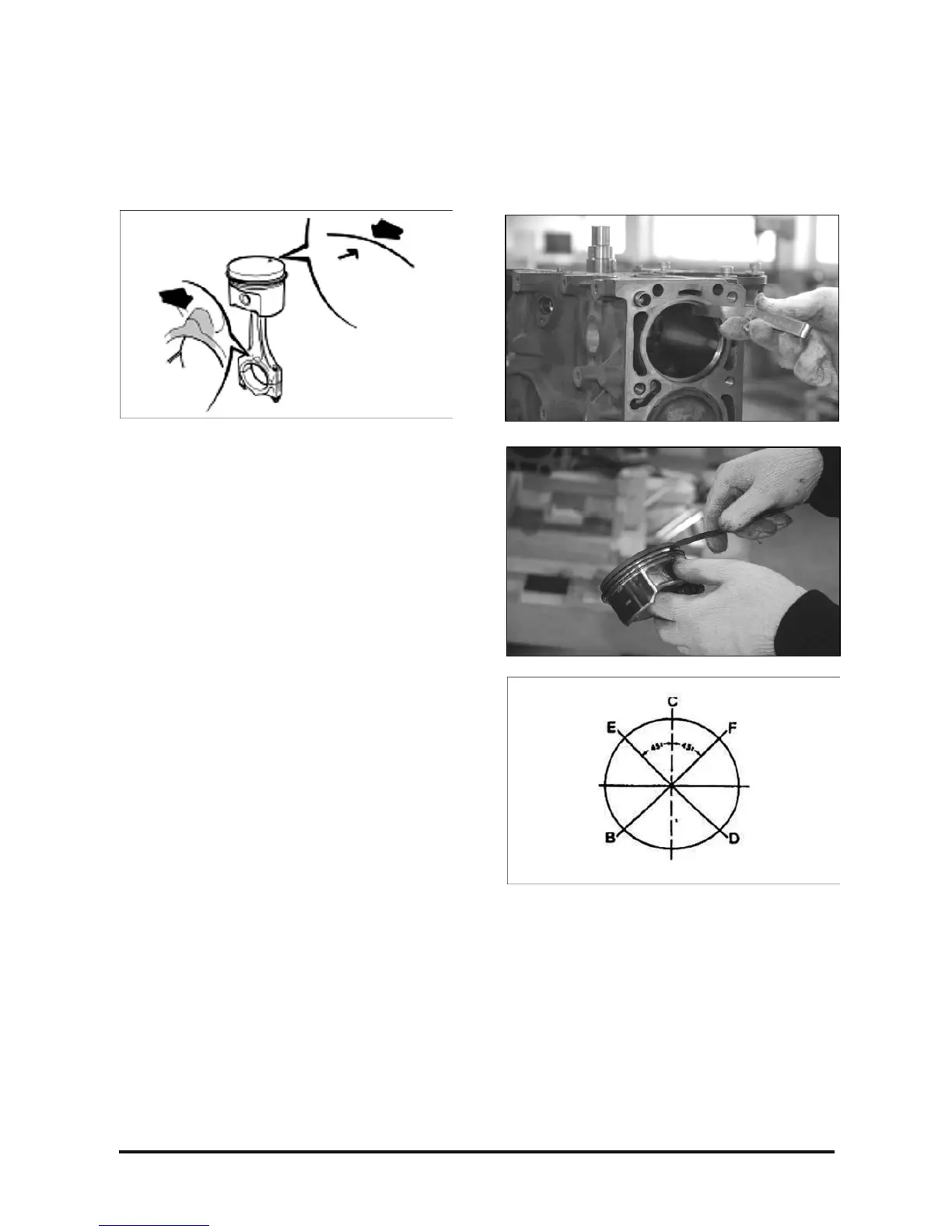
Installation
Install or connect
1. Rings in the piston, following the installation
sequence of the openings and considering that
the vertical dash line (C) corresponds to the pin
position.
B. Oil control ring.
C. Spacer ring.
D. Oil control ring.
E. Lower compression ring.
F. Upper compression ring.
2. Piston-connecting rod assembly in the block, with
the aid of the universal band, positioning the
piston arrow turned toward the engine front end.
Important
• Lubricate the rings and cylinders.
• Simultaneously, guide the connecting rod
bearing with tool T-9806681.