G424F(FE) Service Manual Chapter 3. Engine Mechanical System 73
Important
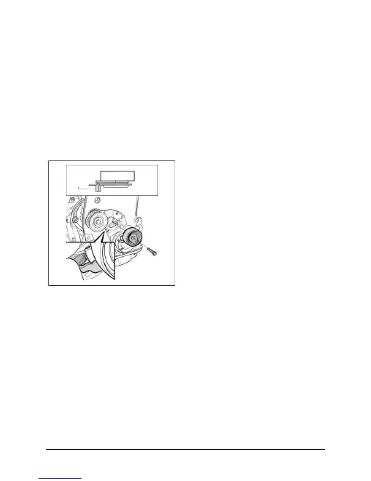
• The Tensioner roller lug (1) should be positioned
in the guide housing (2) of the oil pump case.
12. Crankshaft timing pulley and attaching bolt,
without tightening.
13. With a 17-mm socket and torque wrench.
Tighten
• Bolts: 135 + 30° + 15° (99 lb·ft. + 30° + 15°).
14. Timing pulley rear cover; see “Timing Pulley
Rear Cover – Installation”, in this section.
Oil Pump Assembly
Disassemble
1. Remove the oil pump; see “Oil Pump – Removal”,
in this section.
2. Pump cover, with a proper posi-drive screwdriver.
3. Drive gear.
4. Driven gear.
5. Oil pressure switch, with a 26-mm wrench.
6. Oil filter gallery plug, with a 19-mm combination
wrench.
7. Relief valve plug, with a 24-mm combination
wrench.
8. Sealing washer.
9. Spring.
10. Valve plunger.
Clean
• All pump parts.
Inspect
• Parts for wear.
Measure
Play between the following parts:
• Driven gear and case, which should be 0.11 –
0.19 mm.
• Drive gear and crescent, which should be 0.35 –
0.45 mm.
• Gear and cover, which should be 0.03 – 0.10
mm.
Assemble
1. Plunger in the valve. (1)
2. Spring. (2)
3. Sealing washer. (3)
4. Relief valve plug, with a 24-mm socket wrench
and torque wrench.(4)
Tighten
• Valve plug: 45 – 60 N•m (33 – 44 lb•ft).
5. Driven gear. (5)
6. Drive gear. (6)
7. Oil pump cover and attaching screws, with a posi-
drive screwdriver. (7)
8. Oil pump gallery plug, with a torque wrench. (8)
Tighten
• Gallery plug: 30 – 35 (22 – 25,7 lb·ft)
9. Oil pressure switch, with a 26-mm socket and
torque wrench.