G424F(FE) Service Manual Chapter 3. Engine Mechanical System 79
Tighten
• Nuts: 18 – 22 N·m (13 – 16 lb·ft.)
Obs.: Tighten the intake manifold nuts in a
crisscross sequence, from the center to the ends.
7. Camshaft case assembly; see “Camshaft Case
Assembly – Installation”, in this section.
Valve, Spring or Seal
Removal
Remove or disconnect
1. Camshaft case assembly, as per instructions
under “Camshaft Case Assembly – Removal”, in
this section.
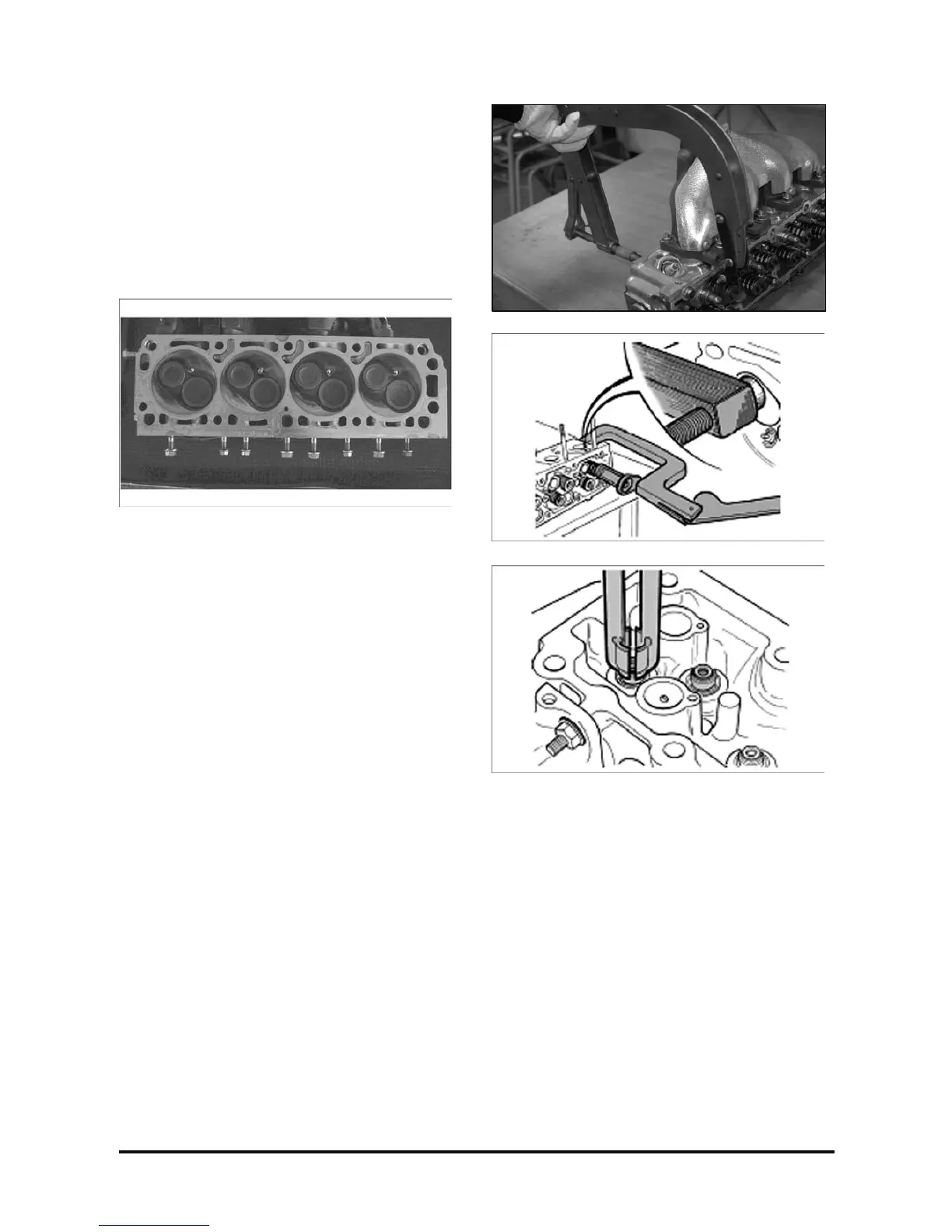
2. Intake manifold-to-cylinder head nuts, with a 13-
mm socket wrench, extension and handle and
remove the manifold.
3. Exhaust manifold-to-cylinder head nuts, with a 13-
mm socket wrench, extension and handle; remove
the exhaust manifold.
4. Valve lock, with the aid of valve spring
compressor.
5. Spring plate.
6. Spring.
7. Seal, with seal pliers.
8. Valve.
Inspect
• Cylinder head for cracks in the exhaust
passages and combustion chambers.
• Valves for head burning, face cracks and
damaged stems.
• Stem lash in the guide, as follows:
Measure the stem diameter in the upper, center
and lower areas.
With the telescope gauge in the valve guide,
measure in the upper, center and lower areas. The
difference in the guide and stem measurements is
the lash.