G424F(FE) Service Manual Chapter 3. Engine Mechanical System 74
Tighten
• Switch: 30 – 50 N·m (22 – 36,7 lb·ft)
10. Install the oil pump; see “Oil Pump – Installation”,
in this section.
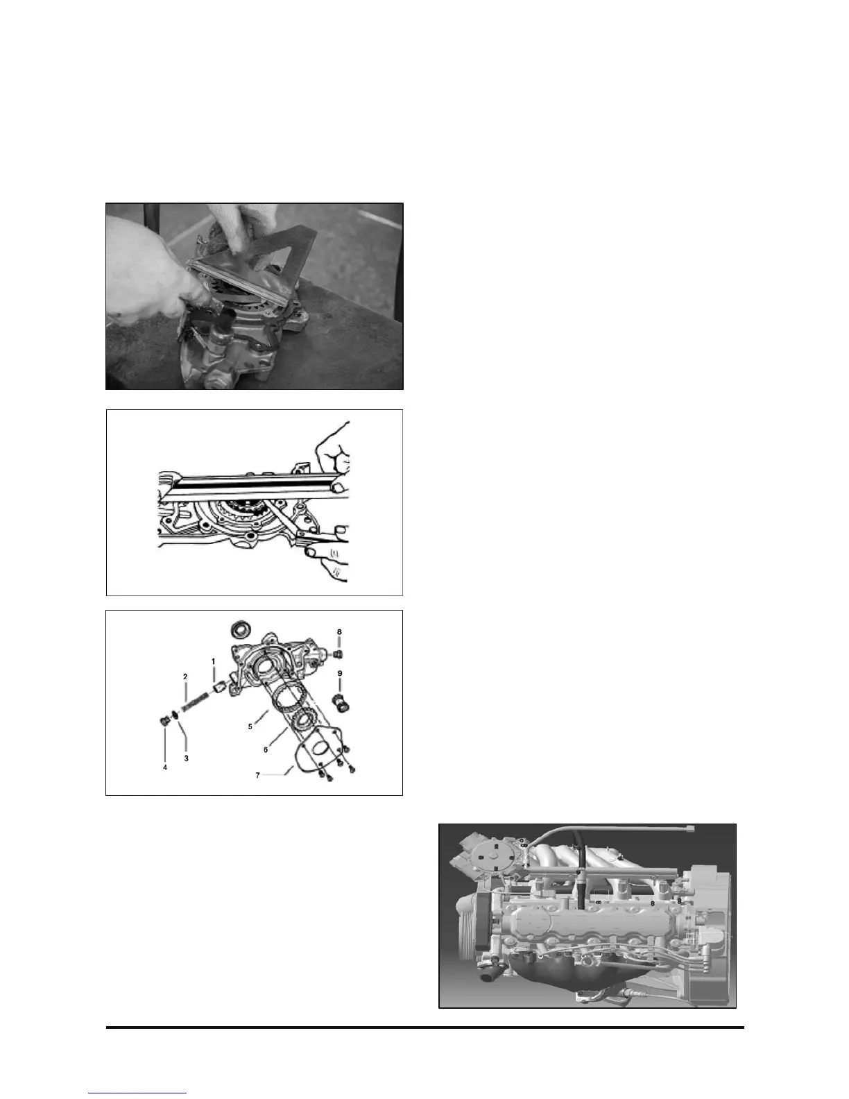
Camshaft Case Assembly
Removal
Remove or disconnect
1. Depressurize the fuel system:
• Fuel-off solenoid valve disconnect.
• Run the engine and leave it running until
stopping by lack of fuel.
• Run the engine for about 5 seconds so as to fully
depressurize the fuel system.
• Fuel pump electric connection, from the tank
upper area
• Run the engine and let it idle until it stops by lack
of fuel.
• Start the engine for about 5 seconds, so as to
obtain full pressure relief in the fuel system.
2. Battery negative cable.
3. Hose connecting the Mixer assembly to the air
cleaner, with an 8-mm socket wrench, extension
and handle; loosen the clamps.
4. Electric harness-to-intake manifold front area
support, with a 10-mm socket wrench, extension
and handle; position the harness so that it does
not obstruct the manifold removal.
5. MAP electric connection, located on the intake
manifold rear area.
6. DIS coil electric connection and spark plug cables.
7. DIS coil attaching bolts, with a 10-mm
combination wrench and handle; remove the DIS
coil.