G424F(FE) Service Manual Chapter 3. Engine Mechanical System 85
Important:
• Whenever the crankshaft is removed, it should
be positioned standing up in the flywheel, to
prevent it from warping.
Engine Assembly
Installation
Install or connect
1. Upper shells in the block; lubricate the surface
turned toward the saddle with engine oil.
2. Crankshaft in the cylinder block.
3. Main bearing caps with the shells lubricated on
the surfaces turned to the saddle.
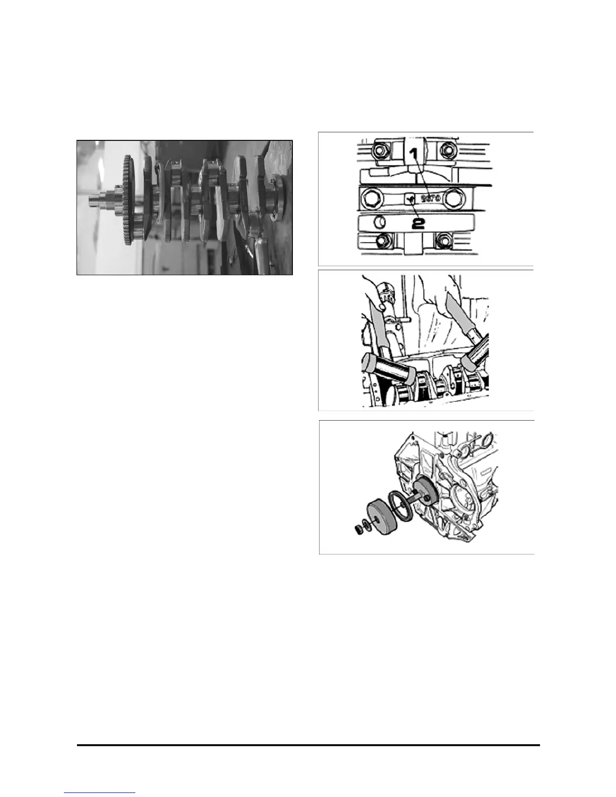
Important
• The bearing caps should be installed so that the
cast number bases (1) stay turned to the engine
rear side. Pay also attention to the engraved
sequence numbers (2).
• Fill the rear bearing cap side grooves with
sealant.
4. Main bearing attaching bolts, without tightening,
with a Torx E12 wrench, extension and handle.
Important
• With a plastic mallet, slightly tap the crankshaft,
on both directions, so as to mainly seat the
thrust bearing rear face.
5. Tighten the main bearing attaching bolts with a
Torx E12 wrench, extension and torque wrench.
Tighten
• Bolts: 50 N·m + 45° + 15°.
6. Crankshaft seal, with tool KM-658.
7. Piston-connecting rod assembly in block, with the
aid of the universal band, position the piston arrow
turned toward the front end of the engine.
Important
• Lubricate the rings and cylinders.
• Simultaneously, guide the connecting rod
bearing with tool T-9806681.
• Install the connecting rod upper shell lubricated
only in the face turned to the bearing journal
and pull the connecting rod until it touches the
journal.