G424F(FE) Service Manual Chapter 3. Engine Mechanical System 80
Important
• If the lash is out of the specification, which is
0.015 – 0.042 mm (intake) and 0.038 – 0.072
mm (exhaust), ream the guide to install an
oversize valve.
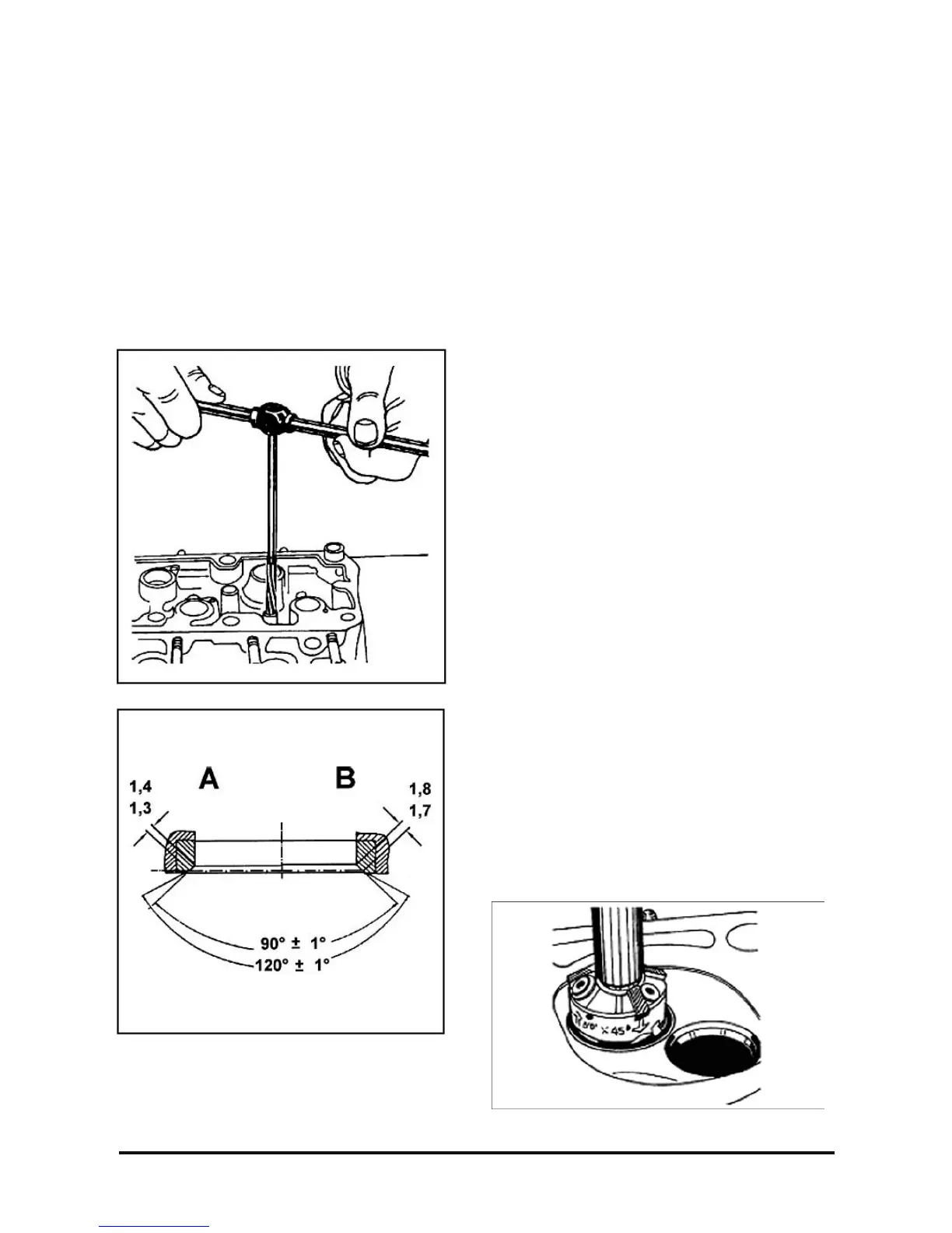
• Valve seat for:
Concentricity between maximum and minimum
readings, which should be 0.05 mm (0.002 in.)
Width, which should be 1.3 – 1.4 mm (intake A) and
1.7 – 1.8 mm (exhaust B)
Important
• If necessary use a 45° ± 3° Valves for corrosion.
Corroded valves, once not excessively worn,
can be refaced by special equipment, as
follows:
Reface them until obtaining a 92 ° ± 15° angle.
The face angle can also be considered
regarding the valve head, which should be 44°.
Installation
Install or connect
1. Valve seal, with the aid of tool KM-352.
2. Spring and spring plate.
3. Valve lock, with the aid of valve spring
compressor.
4. Exhaust manifold with a new gasket to the
cylinder head and use new nuts, without
tightening.
5. With a 13-mm socket wrench, extension and
torque wrench, tighten.
Tighten
• Nuts: 18 – 22 N·m (13 – 16 lb·ft.)
6. Intake manifold with a new gasket to the cylinder
head and use new nuts, without tightening.
7. With a 13-mm socket wrench, extension and
torque wrench, tighten.
Tighten
• Nuts: 18 – 22 N·m (13 – 16. lb·ft.)
8. Camshaft case assembly; see “Camshaft Case
Assembly – Installation”, in this section.